WWW.NORAC.CA
PRECISIONDEFINED
Page20
Visitwww.solutions.norac.caformoresystem
installationandtroubleshootinginfo.
6.4.2. InstallationofaFiveSensorSystem(SevereTerrainOption)
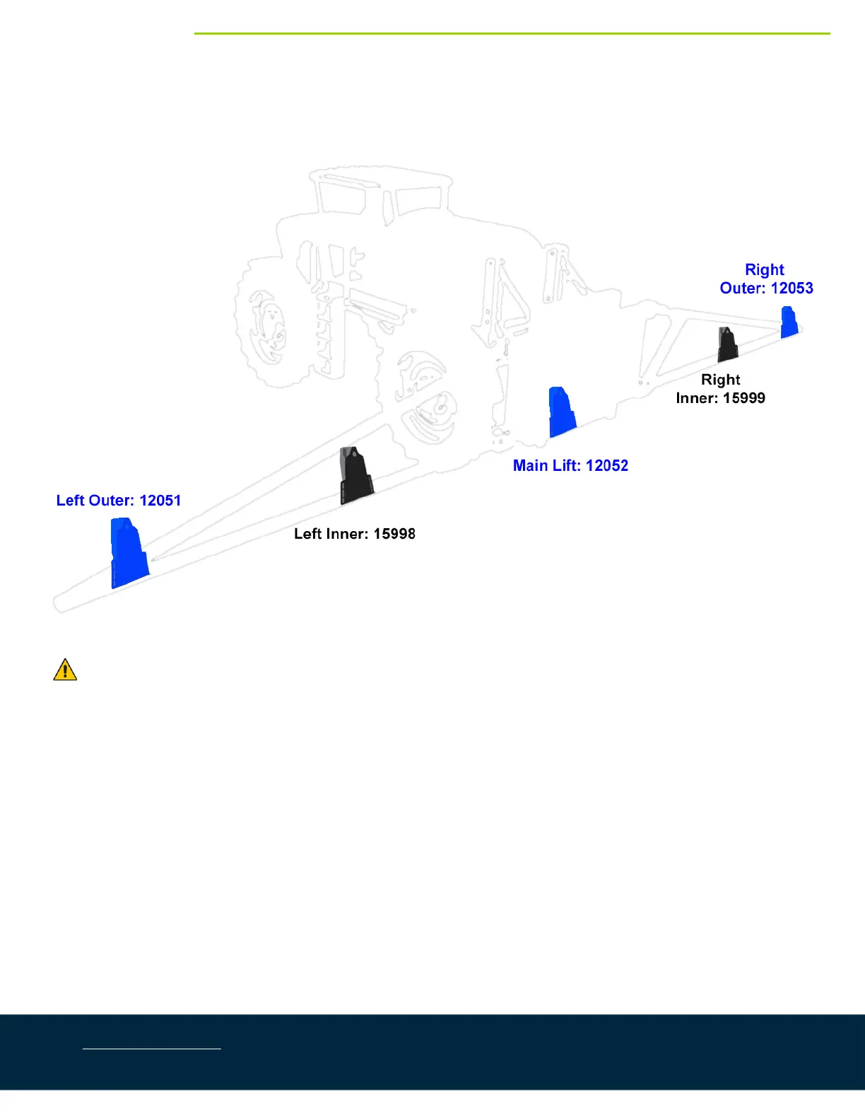
Eachsensorhasaserialnumberstampedonthesensorhousing.
Figure18:SensorSerialNumberArrangement
TheMAXSensors(E07)aremountedinthepositionsshowninblack.
1. Thesensorbracketshouldbeorientedforward(aheadoftheboom).
2. MounttheouterwingsensorbracketsasdescribedinSection6.4.1,step2.
3. Mounttheinnerwingsensorbracketsontotheboomhalfwaybetweenthetipandcenterofthesprayer
(Figure19).
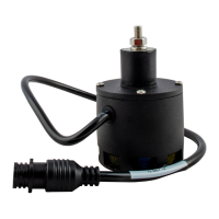
4. MounttheMAXSensors™(E07)intotheinnersensorbracketswiththelowestserialnumberontheleft
sideandthehighestserialnumberontherightside.Runthesensorcable throughholeintheba ckofthe
bracket.
Ensure the cable is clear of moving parts and will not be damaged during folding.The MAX
Sensors(E07)aretallerthantheUltrasonicSensors(E05).
5. MounttheUltrasonicSensors(E05)in theouterwingsensorpositionswiththelowestserialnumberon
theleftsideand the highest
serialnumber on the right side.Runthesensorcablethroughholein the
backofthebracket.Ensurethecableisclearofmovingpartsandwillnotbedamagedduringfolding.