NORDAC FLEX (SK 200E ... SK 235E) – Users Manual for Frequency Inverters
54 BU 0200 en-3118
The output power of the SK BRI4 is limited (see also the following note field) and can be calculated as
follows.
=
∗ (1 +
�
(30 /
)
2
, however, the following applies P < P
max
(P=Brake power (W), P
n
= Continuous brake power of resistor (W), P
max
. peak brake power, t
brake
= duration of
braking process (s))
The permissible continuous brake power P
n
must not be exceeded in the long-term average.
Pos: 105 /A nleit ung en/El e ktr onik /FU und Star ter /2. M ontag e u nd I nst alla tio n/Z ube hör/ Bre ms wider st and/ SK 1 x0E , SK 2xx E/In ter ner Br ems wid erst and SK BR I4- ... INFOR M ATIO N Spi tz enlas t begr enz en - DIP-Schal ter ( S1) [SK 2 xxE] @ 21 \mod_1528365369602_388.docx @ 2424744 @ @ 1
Peak load limitation - DIP switches (S1)
When using internal brake resistors, DIP switches (S1), No. 8 (please see chapter 4.3.2.2 "DIP switches
(S1)")
must be set to "on". This is important for activating a peak output limit for protecting the brake resistor.
Pos: 106 /A nleit ung en/El e ktr onik /FU und Star ter /2. M ontag e u nd I nst alla tio n/Z ube hör/ Bre ms wider st and/ SK 1 x0E , SK 2xx E/El e ktris che Daten (BRI) [SK 2xxE] @ 21\mod_1528374732538_388.docx @ 2424894 @ 5 @ 1
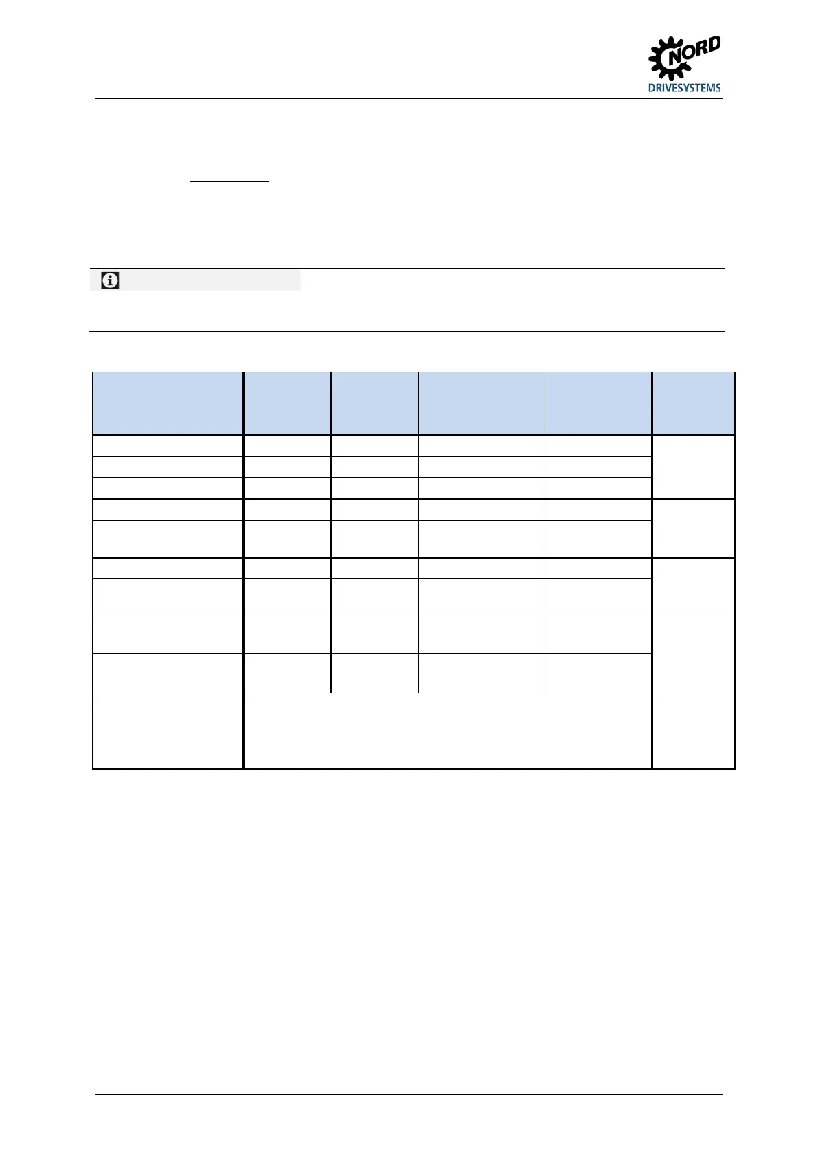
Electrical data
Designation
(IP54)
Part No. Resistance Max. continuous
output / limit
2)
(P
n
)
Power
consumption
1)
(P
max
)
Connecting
cable or
terminals
SK BRI4-1-100-100 275272005
100 Ω
100 W / 25 % 1.0 kWs
Silicone
conductor
2x AWG 20
approx. 60 mm
SK BRI4-1-200-100 275272008
200 Ω
100 W / 25 % 1.0 kWs
SK BRI4-1-400-100 275272012
400 Ω
100 W / 25 % 1.0 kWs
SK BRI4-2-100-200 275272105
100 Ω
200 W / 25 % 2.0 kWs
Silicone
conductor
2x AWG 18
approx. 60 mm
SK BRI4-2-200-200 275272108
200 Ω
200 W / 25 % 2.0 kWs
SK BRI4-3-047-300 275272201
47 Ω
300 W / 25 % 3.0 kWs
conductor
2x AWG 16
approx. 170 mm
SK BRI4-3-100-300 275272205
100 Ω
300 W / 25 % 3.0 kWs
SK BRI4-3-023-600 275272800
3)
23 Ω
(2 x 47 Ω)
600 W / 25 %
(2 x 300 W)
6.0 kWs
(2 x 3 kWs)
Silicone
conductor
2x 2x AWG 16
approx. 170 mm
SK BRI4-3-050-600 275272801
3)
50 Ω
(2 x 100 Ω)
600 W / 25 %
(2 x 300 W)
6.0 kWs
(2 x 3 kWs)
DIP switches (S1),
DIP switch No. 8 = on
1) maximum one-off within 10 s
In order to prevent non-permissible heating of the connection unit, the continuous power
is limited to 1/4 of the rated power of the brake resistor.
This also has a limiting effect on the energy consumption.
3) Set consisting of 2 resistors to be connected in parallel
Pos: 10 7 /Allg emein/ Allg emeing ültig e Mod ule/---------Sei tenumbr uch ko mpakt --------- @ 13\mod_1476369695906_0.docx @ 2265495 @ @ 1
 Loading...


