Do you have a question about the Nordberg A2020 and is the answer not in the manual?
Overview of the Nordberg A2020 system, its components, and applications.
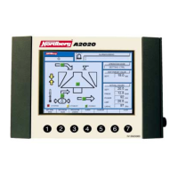
Details on the Display Control Unit (DCU) interface, including display and control keys.
Explanation of the seven windows on the display screen and their functions.
Description of the main menu and its submenus for system navigation.
Description of the crusher control screen functions and indicators.
Guide to selecting operational modes: manual, setting, and load control.
Explanation of manual control mode operation and selection process.
Description of setting control mode, comparing actual vs. preset values.
Explanation of load control mode, comparing pressure and power values.
Details on feeder control via level switch and winter mode operation.
Procedure for setting preset values in setting control mode.
Procedure for setting preset values in load control mode.
Explanation of the trends display for monitoring crusher actual values over time.
Description of field data, including standard measurements and data logging.
Details on alarm indication (color coding) and obtaining more information.
Instructions for navigating through alarm and warning messages.
Procedure for reading alarm and warning data and using function keys.
List of additional information gathered on alarms and warnings.
Instructions for performing manual calibration of the crusher setting.
Description of contact calibration for fine crushers.
Detailed steps for performing manual calibration.
Detailed steps for performing contact calibration.
Overview of the diagnostics display content and related functions.
Procedure for reading trends through the diagnostics menu.
Description of functions for keys in the trend screen.
Procedure for viewing input and output data for sensors and actuators.
Steps to start the crusher lubrication system.
Steps to start the crusher itself.
Steps to start the feeding device.
Steps to stop the feeding device.
Steps to stop the crusher.
Steps to stop the lubrication system.
Procedure for selecting the user interface language.
Procedure for selecting between metric and imperial units.
Procedure for changing the system time and date.
Messages related to setting sensor faults and recovery.
Messages related to pressure sensor faults and peaks.
Messages for lubrication oil temperature in tank faults.
Messages for crusher lubrication return oil temperature faults.
Messages for power measurement faults and limits.
Status of the feeding device safety device and its implications.
Status of the lubrication oil cooler safety device.
Status of the lubrication pump safety device.
Status of the lubrication oil heater safety device.
Status of the adjustment pump safety device.
Status of the crusher safety device.
Faults related to the crusher control circuit cables and connectors.
Faults related to the feeding device control circuit cables.
Faults in lubrication oil heater and cooler control circuits.
Faults in the lubrication pump control circuit cables.
Diagnosis for faults related to setting adjustments.
Diagnosis for filter jam in lubrication oil.
Troubleshooting for process stoppage due to lubrication failure.
Error messages for broken connections between modules.
Error messages related to CAN bus connection issues.
Messages for unreliable modules and software file open failures.
Diagram showing interconnections between PCM, LCM, and DCU.
Schematics for main power, motors, starters, and power components.
Wiring for pumps, fans, heaters, and other auxiliary motors.
Diagrams for crusher motor control, safety circuits, and emergency stops.
Wiring details for the PCM module inputs, outputs, and signals.
Wiring for frequency converters, DCU, LCM communication, and manual control logic.
Wiring details for the LCM module inputs, outputs, and sensor signals.
Index of components and their wiring references.
List of parts for the A2020 system with reference numbers and descriptions.
| Brand | Nordberg |
|---|---|
| Model | A2020 |
| Category | Controller |
| Language | English |