2, 2
Hold the Console Frame (6) near the Uprights (3, 4),
Connect the Upper Wire Harness (75) to the Extension
Wire Harness (76), Attach the Console Frame to the
Uprights with four M8 x 76mm Button Bolts (112) and
four M8 Nylon Locknuts (102); make sure not to
pinch the Wire Harnesses.
Slide an M8 x 28mm Washer (99) onto an M8 x 20mm
Button Screw (113), Tighten the Button Screw into one
end of the Incline Axle (40), Apply a small amount of
the included grease to the Incline Axle,
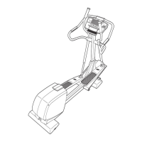
Orient the Incline Ramp (5) so that the straight end is
down by the Frame (1) as shown, Fit the welded tube
on the bottom of the Incline Ramp between the two
rings on the top of the Frame, insert the Incline Axle
(40) through the rings and the welded tube,
Slide an M8 x 28mm Washer (99) onto an M8 x 20mm
Button Screw (113), Tighten the Button Screw into the
open end of the Incline Axle (40),
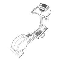
Using your fingers, turn the shaft on top of the Lift
Motor (42) counterclockwise until it stops turning,
Position the U-bracket on the bottom of the Incline
Ramp (5) over the end of the shaft as shown, Next, fit
an Incline Motor Spacer (60) on each side of the shaft
between the shaft and the U-bracket,
insert the Short Clevis Pin (118) through the U=
bracket on the Incline Ramp (5), the shaft on the Lift
Motor (42), and both of the Incline Motor Spacers (60),
insert the straight end of a Hairpin (71) into the end of
the Short Clevis Pin,
75
76
113
112
02
Do not pinch the
wire harnesses
during this step.
\,
,\
I I
/ i
/ /
/
/
/
/
99 1"
Front View
6

 Loading...