4131133A
1
2
3
4
4131145A
1
2
Overview
A 2-4
E 2000 Nordson Corporation
All rights reserved
41-3000
Issued 11/00
A2EN-02-[3-OVER]–2
The major mechanical components of a Series 3100 melter are the tank,
the pump, and the manifold.
The tank holds a large supply of adhesive and melts it before it is
pumped to the hoses and guns. Series 3100 melters have a tank only.
The term “tank” is used to mean the tank strainer, and the melting fins
collectively, including the location of the tank and grid heater connectors.
See Figure A 2-3.
Refer to the Technical Data section for the tank storage capacity and
other key information about the tank.
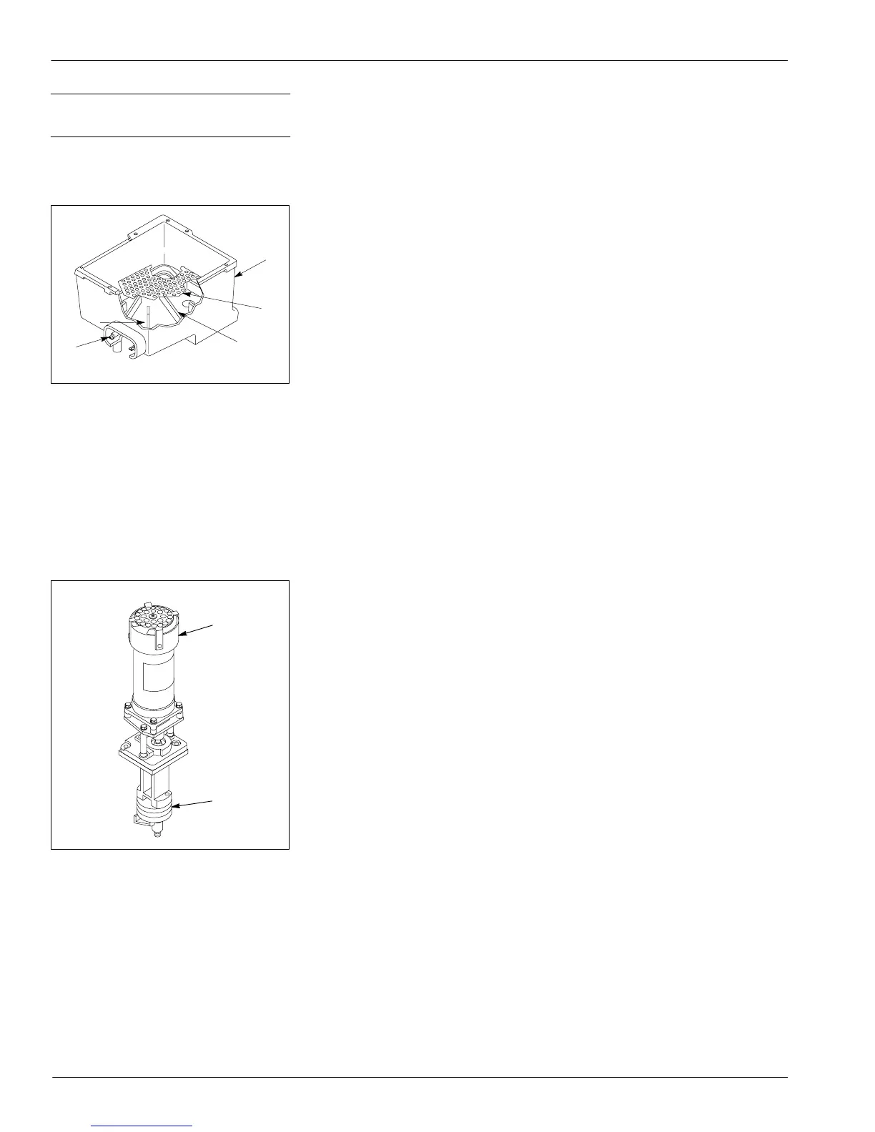
Fig. A 2-3 Key Parts of the Tank
1. Tank
2. Tank strainer
3. Melting fins
4. Heater connectors
The pump delivers the melted adhesive from the tank through the
manifold and hoses to the guns. The key parts of an AC gear pump are
the gear pump and the AC gear motor. Figure A 2-4 shows the key parts
of the pump.
Refer to the Technical Data section for the pump delivery rate and other
key information about the pump.
Fig. A 2-4 Key Parts of the AC Gear
Pump
1. AC gear motor
2. Gear pump
3. Overview of the
Mechanical Components
Tank
Pump

 Loading...


