7
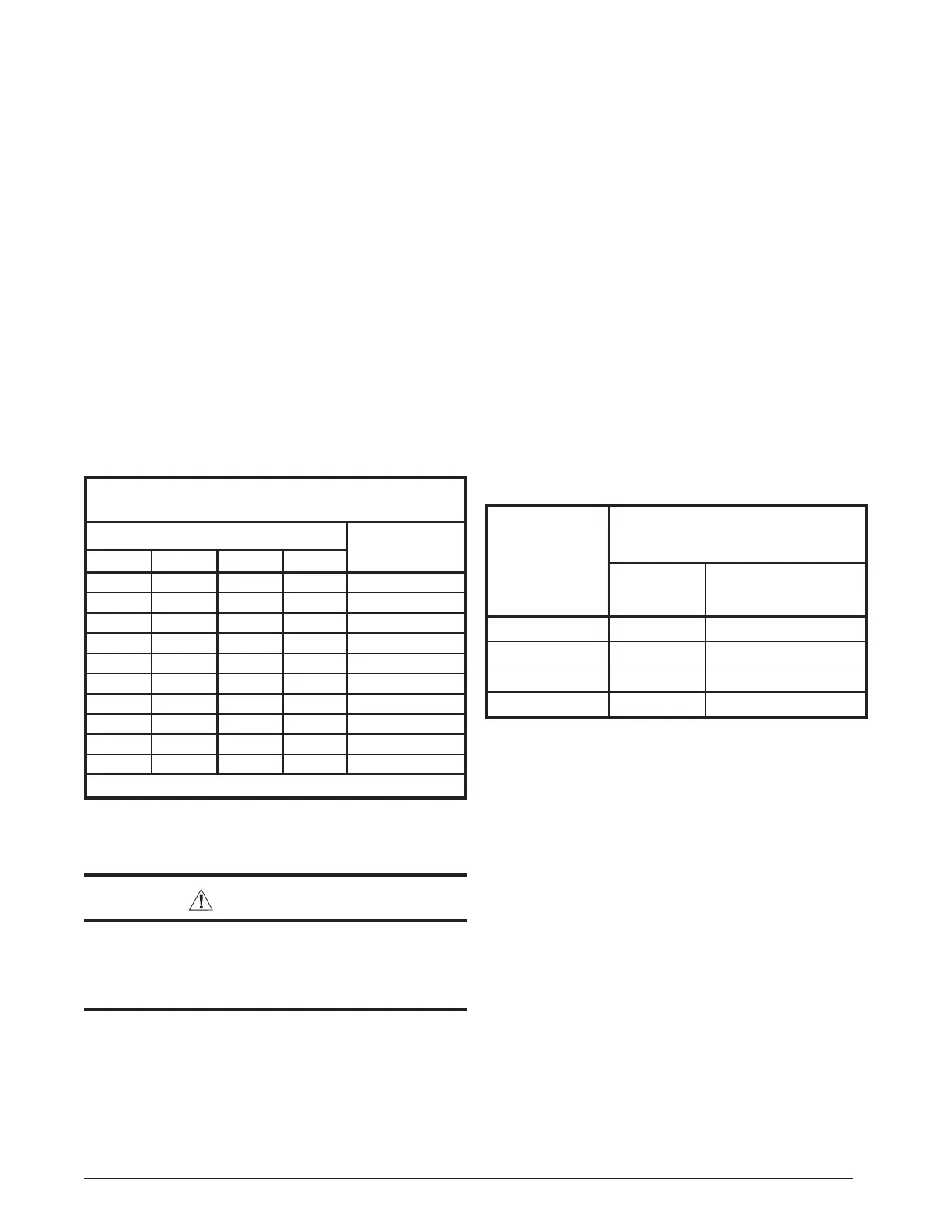
COPPER WIRE SIZE — AWG
(1% Voltage Drop)
Supply Wire Length-Feet
Supply Circuit
Ampacity
200 150 100 50
6 8 10 14 15
46812 20
46810 25
44610 30
3468 35
3468 40
2346 45
2346 50
2346 55
1234 60
Wire Size based on N.E.C. for 60° type copper conductors.
Table 1. Copper Wire Size
rating label and according to applicable local codes.
See the unit rating plate for minimum circuit ampacity
and maximum overcurrent protection limits.
• Provide power supply for the unit in accordance with the
unit wiring diagram, and the unit rating plate. Connect
the line-voltage leads to the terminals on the contactor
inside the control compartment.
• Use only copper wire for the line voltage power supply
to this unit as listed in Table 1. Use proper code agency
listed conduit and a conduit connector for connecting
the supply wires to the unit. Use of rain tight conduit
is recommended.
• 208/230 Volt units are shipped from the factory wired
for 230 volt operation. For 208V operation, remove the
lead from the transformer terminal marked 240V and
connect it to the terminal marked 208V.
• Optional equipment requiring connection to the power
or control circuits must be wired in strict accordance
of the NEC (ANSI/NFPA 70), applicable local codes,
and the instructions provided with the equipment.
Thermostat Connections
• Thermostat connections should be made in accordance
with the instructions supplied with the thermostat and
the indoor equipment.
• The outdoor unit is designed to operate from a 24 VAC
Class II control circuit. The control circuit wiring must
comply with the current provisions of the NEC (ANSI/
NFPA 70) and with applicable local codes having
jurisdiction.
• The low voltage wires must be properly connected to
the units low voltage terminal block. Recommended
wire gauge and wire lengths for typical thermostat
connections are listed in Table 2.
• The thermostat should be mounted about 5 feet
above the fl oor on an inside wall. DO NOT install the
thermostat on an outside wall or any other location
where its operation may be adversely affected by radiant
heat from fi replaces, sunlight, or lighting fi xtures, and
convective heat from warm air registers or electrical
appliances. Refer to the thermostat manufacturer’s
instruction sheet for detailed mounting and installation
information.
Table 2. Thermostat Wire Gauge
Thermostat
Wire Gauge
Recommended T-Stat Wire
Unit to T-Stat (Length in FT)
2-Wire
(Heating)
5-Wire
(Heating/Cooling)
24 55 25
22 90 45
20 140 70
18 225 110
Grounding
WARNING:
The unit cabinet must have an uninterrupted or
unbroken electrical ground to minimize personal
injury if an electrical fault should occur. Do not
use gas piping as an electrical ground
!
This unit must be electrically grounded in accordance
with local codes or, in the absence of local codes, with
the National Electrical Code (ANSI/NFPA 70) or the CSA
C22.1 Electrical Code. Use the grounding lug provided in
the control box for grounding the unit.
 Loading...