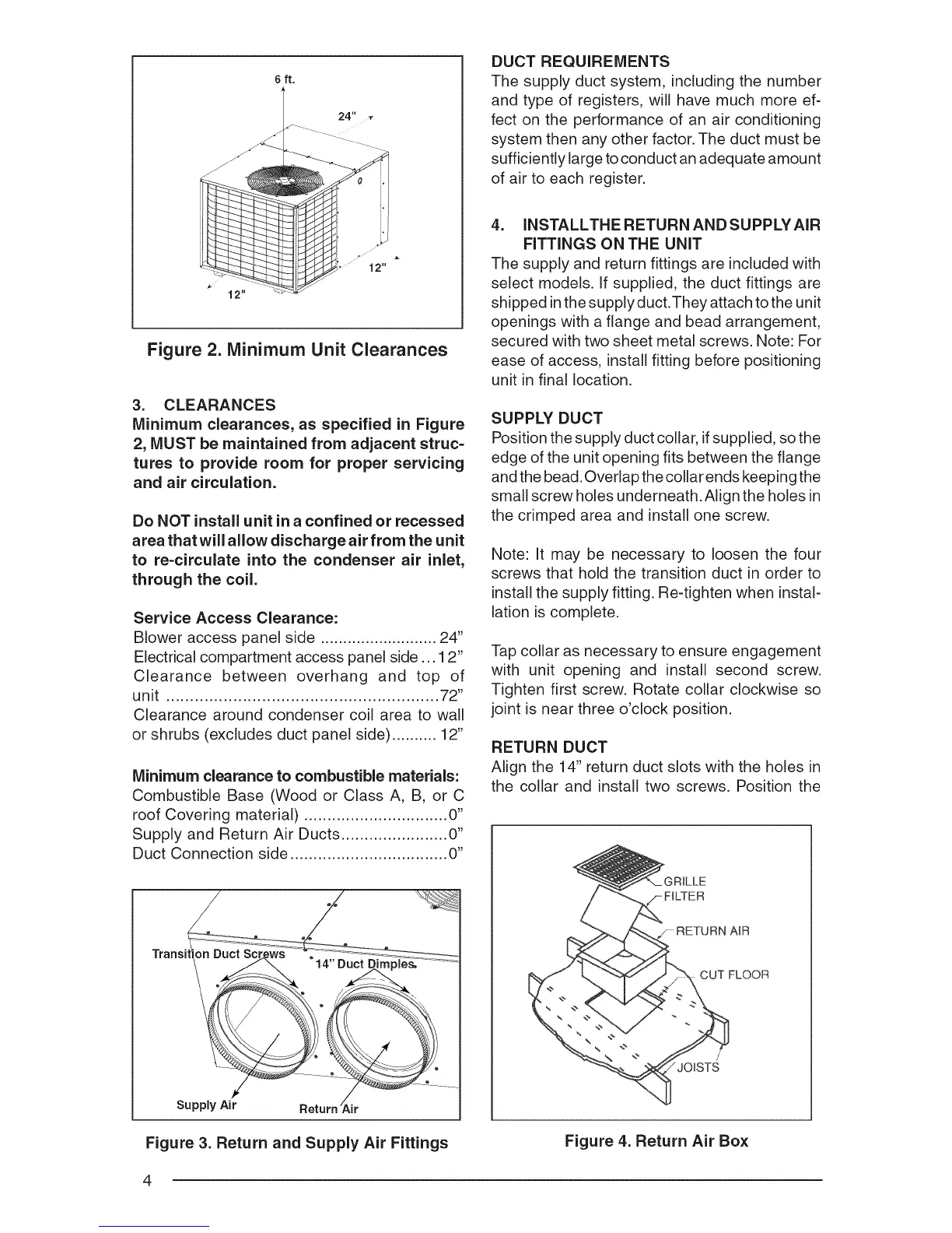
Figure 2. Minimum Unit Clearances
3. CLEARANCES
Minimum clearances, as specified in Figure
2, MUST be maintained from adjacent struc-
tures to provide room for proper servicing
and air circulation.
Do NOT install unit in a confined or recessed
area that will allow discharge air from the unit
to re-circulate into the condenser air inlet,
through the coil.
Service Access Clearance:
Blower access panel side .......................... 24"
Electrical compartment access panel side... 12"
Clearance between overhang and top of
unit ......................................................... 72"
Clearance around condenser coil area to wall
or shrubs (excludes duct panel side) .......... 12"
Minimum clearance to combustible materials:
Combustible Base (Wood or Class A, B, or C
roof Covering material) ............................... 0"
Supply and Return Air Ducts ....................... 0"
Duct Connection side .................................. 0"
Tran _ _
Figure 3. Return and Supply Air Fittings
DUCT REQUIREMENTS
The supply duct system, including the number
and type of registers, will have much more ef-
fect on the performance of an air conditioning
system then any other factor. The duct must be
sufficiently large toconduct an adequate amount
of air to each register.
4. INSTALLTHE RETURN AND SUPPLYAIR
FITTINGS ON THE UNiT
The supply and return fittings are included with
select modeEs. If supplied, the duct fittings are
shipped in the supplyduct.They attach tothe unit
openings with a flange and bead arrangement,
secured with two sheet metal screws. Note: For
ease of access, install fitting before positioning
unit in final location.
SUPPLY DUCT
Position the supply duct collar, if supplied, so the
edge of the unit opening fits between the flange
and the bead. Overlap the collar ends keeping the
small screw holes underneath. Align the holes in
the crimped area and install one screw.
Note: It may be necessary to loosen the four
screws that hold the transition duct in order to
install the supply fitting. Re-tighten when instal-
lation is complete.
Tap collar as necessary to ensure engagement
with unit opening and install second screw.
Tighten first screw. Rotate collar clockwise so
joint is near three o'clock position.
RETURN DUCT
Align the 14" return duct slots with the holes in
the collar and install two screws. Position the
7 RETURN AiR
CUT FLOOR
Figure 4. Return Air Box
4
 Loading...