CONNECTING THE RETURN AND SUPPLY
AIR FLEXIBLE DUCTS
a. The supply duct for all units is 12" in diam-
eter. The return duct is 14" diameter for all
air conditioning units.
b. The flexible ducts can be connected to the
corresponding fittings with the clamps pro-
vided with the ducts. Note: All connections
should be leak tight or a loss in cooling
capacity will result.
c. The flexible ducts may be cut to the required
length, see instructions packed with duct.
Keep all ducts as short and straight as pos-
sible. Avoid sharp bends.
d. Ducts may be spliced with sheet metal
sleeves and clamps. (See Ducting Instal-
lation Accessories page 6.)
e. Once the inner duct is connected to the
proper fitting, the insulation and plastic
sleeve should be pulled over the connection
and clamped.
f. For homes with multiple supply ducts or for
special applications, a Y fitting is available
to divide the supply air so it can be ducted
to different areas of the home for more ef-
ficient cooling. Note: TheY fitting should be
insulated for maximum performance.
Model Wire Color/ Motor Air Flow
P3RD Speed Tap Speed (0.3 in.WC)
Red
2Ton
Black
Red
2.5 Ton
Black
Red
3Ton
Black
Low 760
High* 1000
Low 760
High* 1000
Low 760
High* 1000
T1 Low 750
T2 Med/Low 1,000
3.5 Ton Orange / T3 Medium* 1,140
Red / T4 Med/High* 1,300
T5 High 1,350
T1 Low 1,340
Orange / T2 Med/Low* 1,450
4 Ton Red / T3 Medium* 1,650
T4 Med/High 1,750
T5 High 1,965
T1 Low 1,340
T2 Med/Low 1,450
5 Ton Orange / T3 Medium* 1,650
Red / T4 Med/High* 1,750
T5 High 1,965
* Factory Setting
Figure 7. Standard Motor Lead Connection
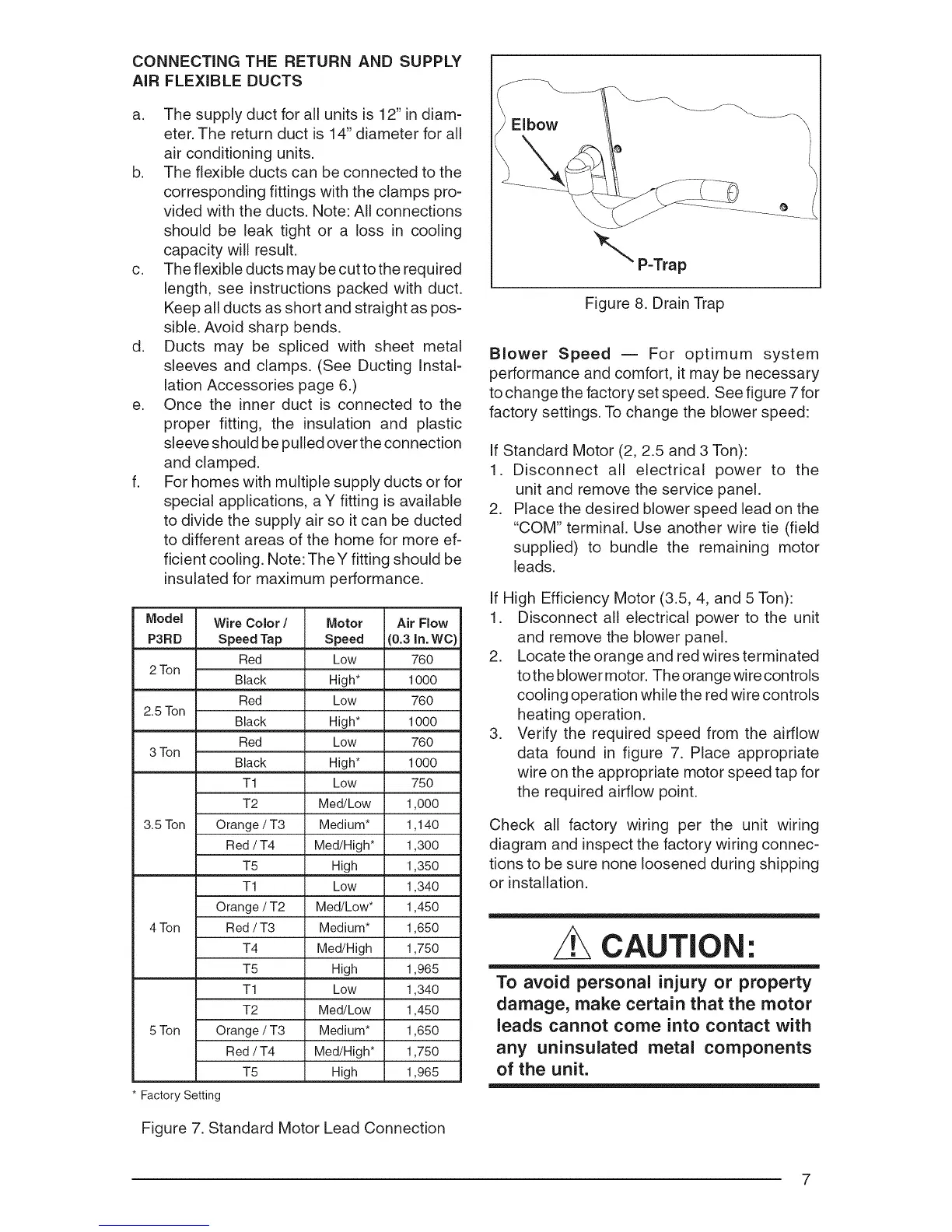
_ Elbow
_"" P-Trap
Figure 8. Drain Trap
Blower Speed -- For optimum system
performance and comfort, it may be necessary
to change the factory set speed. See figure 7 for
factory settings. To change the blower speed:
If Standard Motor (2, 2.5 and 3 Ton):
1. Disconnect all electrical power to the
unit and remove the service panel.
2. Place the desired blower speed lead on the
"COM" terminal. Use another wire tie (field
supplied) to bundle the remaining motor
leads.
If High Efficiency Motor (3.5, 4, and 5 Ton):
1. Disconnect all electrical power to the unit
and remove the blower panel.
2. Locate the orange and red wires terminated
to the blower motor. The orange wire controls
cooling operation while the red wire controls
heating operation.
3. Verify the required speed from the airflow
data found in figure 7. Place appropriate
wire on the appropriate motor speed tap for
the required airflow point.
Check all factory wiring per the unit wiring
diagram and inspect the factory wiring connec-
tions to be sure none loosened during shipping
or installation.
CAUTION'.
To avoid personal injury or property
damage, make certain that the motor
leads cannot come into contact with
any uninsulated metal components
of the unit.
 Loading...