71
5) Open the hot water valve and the water
supply valve.
Check that water does not leak from the
water drain valves.
3) Clean the water filters with a brush under
running water.
4) Reattach the water drain valves (with water
filter).
NOTE
Do not to lose the O-Ring.
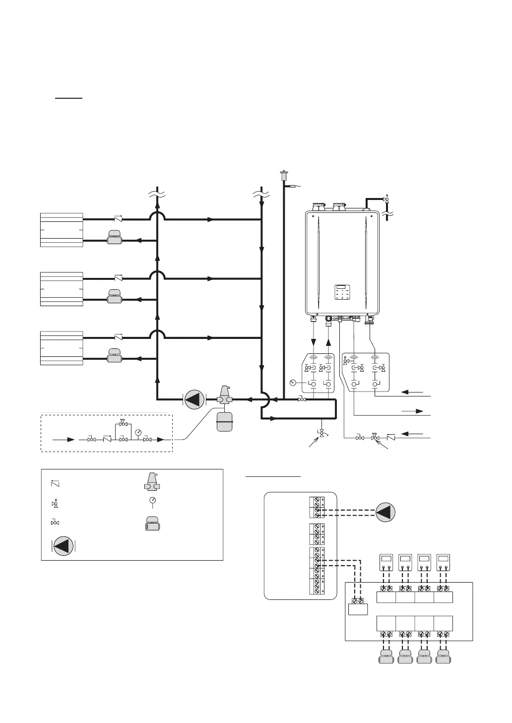
DHW Cold Water Suppl
DHW Hot Water Supply
Auto Feeder Supply
ZONE 1
ZONE 2
ZONE 3
(Pre-charged : 12 psi)
LWCO (Optional)
Zone1
For Additional Zone
Zone2Zone3
Zone#
Zone
Valve1
Zone
Valve2
Zone
Valve3
Zone
Valve#
ZONE CONTROLLERT - T
...
...
7 57 57 57 5
Thermostat (T-T)
Wiring Terminal on the Computer Board
[I:09_EPP]
External Pump function
should be activated by
set installer mode.
*
1
Pressure Reducing Valve
(Less than 30 psi)
*
2
Make up water
Incase of External Water Feeder Usage
Wiring Diagram
[CN237]
Pump
[CN233]
T - T
Pressure Relief Valve
Pressure Gauge
Check Valve
(Back Flow Preventer)
Air Separator
Zone Valve
Expansion Tank
CirculationPump
(Circulator)
System Purge Ball Valve
Ball Valve
To drain outlet
*1 Noritz stocks the “Manifold Kit” for easy heating
installation.
The “Manifold Kit” allows to install primary and
secondary heating loop easier and has shut off
valves and service ports for connecting hoses.
Refer to the Combi Boiler’s Installation Manual for
detail information.
*2 Noritz stocks the “Isolation Valve (Service Valve
Kit)” for easy DHW installation.
The “Isolation Valve (Service Valve Kit)” is
necessary for flushing the Plate Heat Exchanger.
[Typical Heating and DHW diagram]
Water Filling and Trial Operation