76
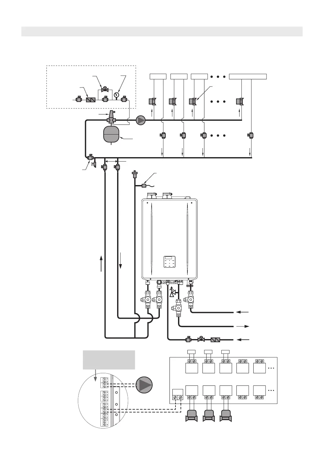
18.3 Zoned with Valves
This drawing is meant to show system piping concept only. Installer is responsible for all equipment & detailing
required by local codes. Refer to page 51 for electrical wiring instructions.
Heating
Return
Heating Supply
ZONE1
ZONE
VALVE
T/T
T/T
DHW Supply
Auto Feeder
ZONE2
ZONE
VALVE
ZONE3
ZONE
VALVE
ZONE1ZONE2
ZONE CONTROLLER
EXTERNAL
PUMP
ZONE3
T/T
[I:09 EP] should be
“ON” in lnstaller Mode to
activate this terminal.
DHW Cold Water Supply
Recommended Pressure Setting: 15-30 ps
T/T
[CN237]
Pump
[CN233]
T - T
ZONE 1
ZONE VALVES
(TYPICAL)
EXTERNAL
PUMP
* In case of installing external water feeder.
ZONE 2 ZONE 3
Additional Zone
AIR SEPARATOR
BALL VALVE
(TYPICAL)
EXPANSION
TANK
Not to exceed 4 pipe Dia or Max. 12 in. APART
Not to install an external pump upstream
an expansion tank in heating supply pipe.
PRESSURE
GAUGE
PRESSURE
REDUCING VALVE
BACKFLOW
PREVENTER
MAKE UP WATER
Optional LWCO
(See on the page 44)
Plumbing Applications