307UM0200_01 May 2016 PD27x User Manual Page 19 of 30
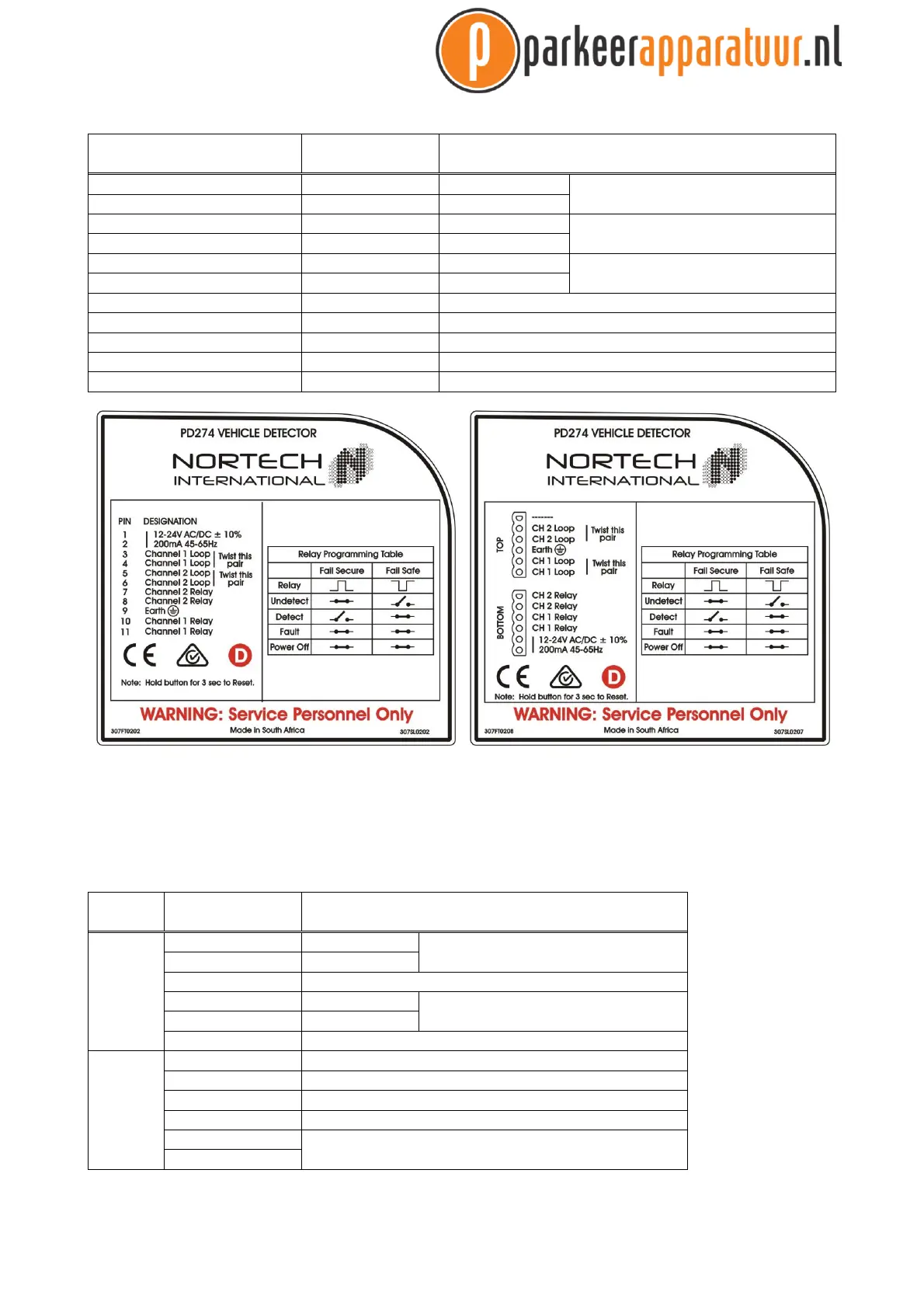
6.3 PD274 Enhanced Detector - Order number 307FT0202
11-pin connector wiring for PD274 DETECTOR - Order number 307FT0202
302FT0041 Wiring Harness
Wire COLOUR
11 PIN Connector
Pin No.
FUNCTION
Red 1 Live Power supply
12-24V ± 10% DC/AC
Black 2 Neutral
Blue 3 Channel 1 Loop
Twist this pair
Blue 4 Channel 1 Loop
Yellow 5 Channel 2 Loop
Twist this pair
Yellow 6 Channel 2 Loop
Grey 7 Channel 2 Relay
Grey 8 Channel 2 Relay
Green/Yellow 9 Earth
White 10 Channel 1 Relay
White 11 Channel 1 Relay
Figure 8. Example of PD27x Side Labels. Power supply requirements and pin connecons are clearly stated on the side of the
unit. 11 Pin configuration is shown on the le, DIN Rail on the right.
6.4 PD271 Enhanced Detector DIN Rail - Order number 307FT0206
DIN Rail connector wiring for PD271 DETECTOR - Order number 307FT0206
6 PIN Connector
Pin No.
FUNCTION
Top
1 Channel 1 Loop
Twist this pair
2 Channel 1 Loop
3 Earth
4 Channel 2 Loop
Twist this pair
5 Channel 2 Loop
6 Not Connected
Boom
7 Channel 2 Relay
8 Channel 2 Relay
9 Channel 1 Relay
10 Channel 1 Relay
11 Power supply
120V AC ± 10% 50/60Hz
12