2-12 DPP Hardware
297-1001-019 Standard 02.01 April 1997
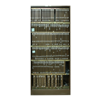
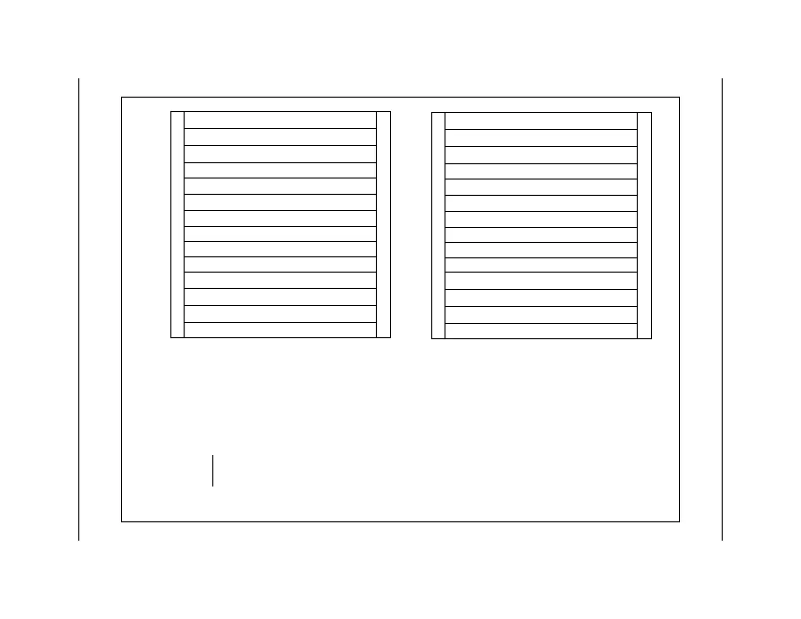
Figure 2-7
Printed Circuit Assembly identifiers and locations
A2 EPROM PCA
A1 CPU LOGIC PCA
A6 QUAD SIO PCA
A5 ERROR CONTROL II PCA
A7 56K INTERFACE PCA*
A4
A8
A9
A10
A3 MEMORY EXPANSION PCA
A11 DISK/SCSI INTERFACE PCA
A12 DATA STREAM INTERFACE PCA
A13 DATA STREAM INTERFACE PCA
A14 BUS TERMINATOR PCA
Reference designation A and B are
shown for clarity. They are not
printed on the equipment.
* Equipped if the DPP is a Turbo system.
NOTE:
Processor B
Processor A
B1 CPU LOGIC PCA
B2 EPROM PCA
B3 MEMORY EXPANSION PCA
B4
B5 ERROR CONTROL II JUMPER PCA
B6 QUAD SIO PCA
B7 56K INTERFACE PCA*
B8
B9
B10
B11 DISK/SCSI INTERFACE PCA
B12 DATA STREAM INTERFACE PCA
B13 DATA STREAM INTERFACE PCA
B14 BUS TERMINATOR PCA
 Loading...