DPP Hardware 2-19
DPP Product Guide DPP001 and up
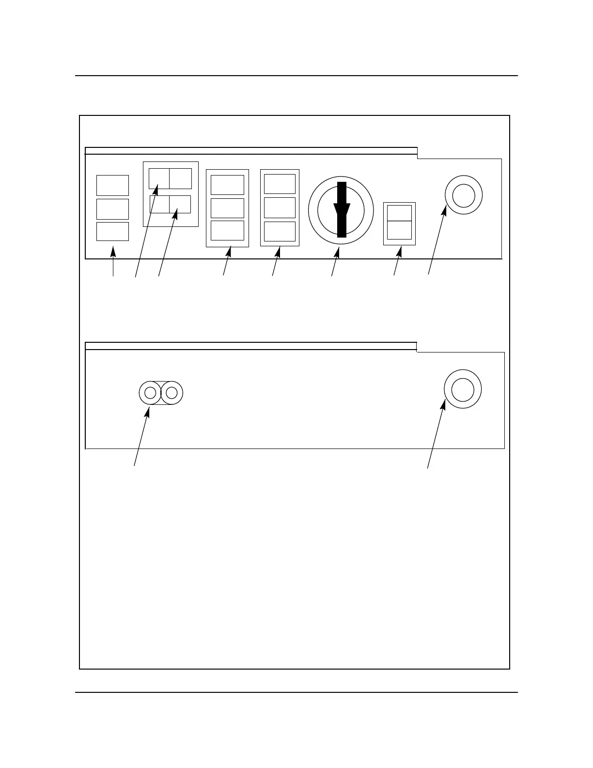
Figure 2-11
DPP Switch and status panel
Switch and Status Panel
A
PRI
AB
OP
123
ALM
PRI
ONL
B
4
MAJ
MIN
CRIT
5
LT
6
7
CHAS.
GND.
8
CHAS.
GND.
8
ROVER Interface Panel
ROVER
XMIT RCV
9
LEGEND:
1 A Processor Status Lamps 5 System Status Lamps
ALM = Alarm CRIT = Critical
PRI = PRIME Mode MAJ = Major
ONL = ONLY Mode MIN = Minor
2 A/B Processor Select Switch 6 Mode Key Switch (optional)
3 ONLY/PRIME Mode Select Switch 7 Lamp Test Switch
4 B Processor Status Lamps 8 Jack for ESD Ground Strap
Connection
ALM = Alarm
PRI = PRIME Mode 9 Rover Jacks (for EAT)
ONL = ONLY Mode (optional)
ALM
ONL
 Loading...