DPP Hardware 2-11
DPP Product Guide DPP001 and up
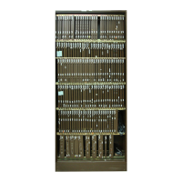
Circuit assembly racks
Typical subassembly and circuit assembly locations are shown in Figure 2-7.
The illustration shows that two PCA racks (A and B) are used. PCAs are
designated A1 through A14 in the A (upper) chassis; B1 through B14 in the B
(lower) chassis. The A and B prefix designations are not marked on the
equipment. Figure 2-7 provides the PCA identifiers and locations.
A backplane circuit assembly comprises the rear of the card rack. The
backplane circuit assembly provides the sockets for the installation and
interconnection of the PCAs. Sockets are numbered, from left to right, 1 to
14 in each chassis. The backplane circuit assembly provides the
interconnections between the plug-in PCAs and the other circuit assemblies
and subassemblies in each DPP chassis.
All DPP equipment employs a standard complement of circuit assemblies to
provide basic system operation. The following PCAs are rack-mounted in
DPP systems:
• two - CPU Logic PCAs
• two - EPROM PCAs
• two - Memory Expansion PCAs
• one - Error Control II PCA (A chassis)
• one - Error Control II Jumper PCA (B chassis)
• two - Quad Serial Input/Output (SIO) PCAs
• two - 56K Interface PCAs (Turbo DPPs only)
• two - Disk Interface (Non-Turbo DPPs) or SCSI Interface PCAs (Turbo
DPPs)
• four - Data Stream Interface (DSI) PCAs
• two - Bus Terminator PCAs.
 Loading...