2-14 DPP Hardware
297-1001-019 Standard 02.01 April 1997
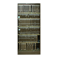
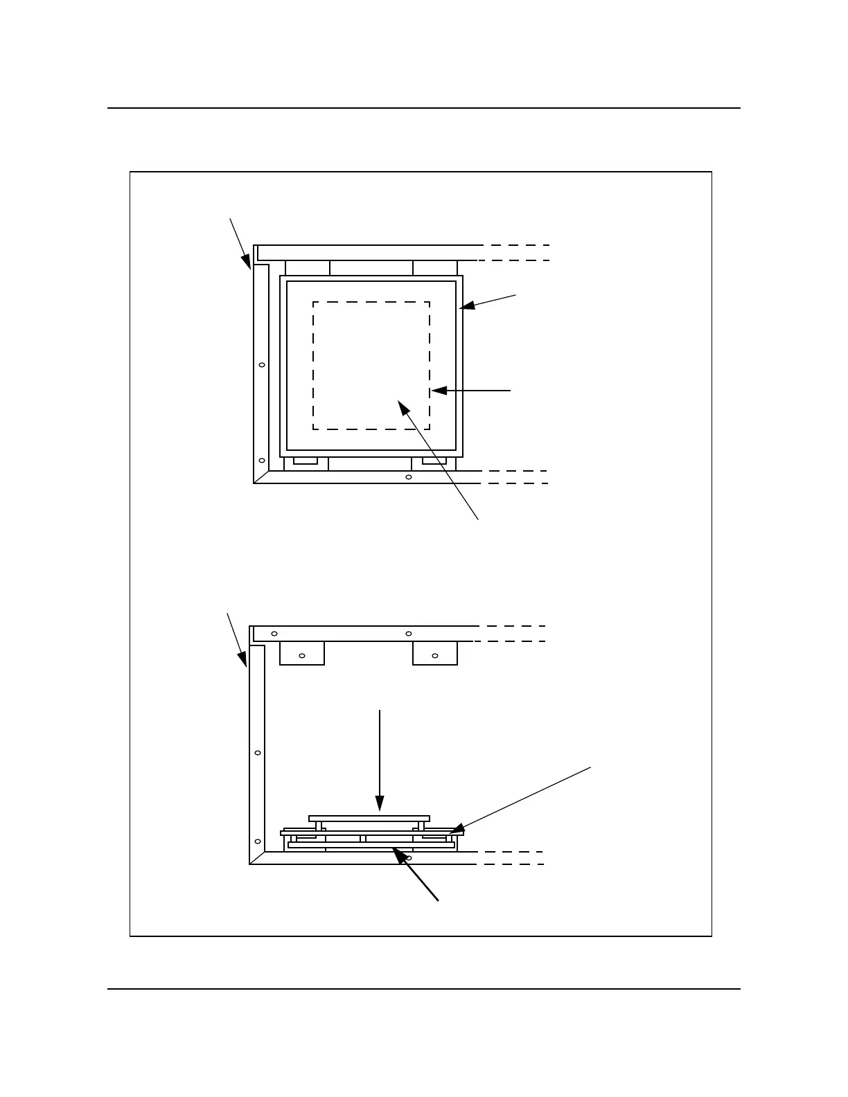
Figure 2-8
Auxiliary circuit assembly locations
Left rear of chassis
(with cabinet back removed)
Disk/SCSI Crossover PCA
(A15 and B15)
(opposite side of hinged panel)
Power and Alarm
Communications PCA (A16)
or optional 56K Crossover
PCA (B16)
Hinged card panel
(closed)
a. View with hinged card panel closed
Left rear of chassis
(with cabinet back removed)
b. View with hinged card panel open
Disk/SCSI Crossover PCA
(A15 and B15)
Power and Alarm Communications PCA
(A16) or
optional 56K Crossover PCA (B16)
Hinged card panel
(open)
 Loading...