2-18 DPP Hardware
297-1001-019 Standard 02.01 April 1997
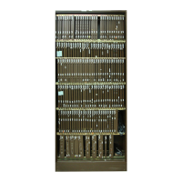
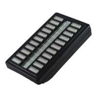
Switch and status panel/rover interface panel
This DPP option uses the upper Switch and Status Panel (A chassis) and the
Rover Interface Panel (B chassis), which provide status information and
manual controls, and Rover terminal interface. The Switch and Status Panel
is built directly into the upper right portion of the A chassis. The Rover
Interface Panel is built into the upper right portion of the B chassis, as
illustrated in Figure 2-11. There are four different DPP configurations
available on the interface panel - Switch/Rover, Switch/No Rover, No Switch/
Rover, and No Switch/No Rover.
 Loading...