Do you have a question about the Nortel DMS-250 and is the answer not in the manual?
Describes the standardized, all-digital characteristics of PRI support for Q.931.
Explains the role of protocols in governing format, timing, and sequencing between terminal stations.
Details the seven-layer OSI reference model architecture used for ISDN protocol.
Explains how layers 1 through 3 govern connection, setup, and transmission of information.
Overview of how DMS-250 switch connects a DS-1 trunk to a single-line PBX.
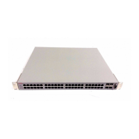
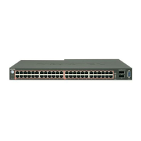
Describes the printed circuit board hardware for DS-1 trunks on the ISDN digital trunk controller (DTCI) shelf.
Outlines requirements for frame formats, channel ordering, line coding, and test equipment.
Details the DS-1 basic frame format, bit rate, sampling rate, and superframe format.
Presents the channel ordering sequence for DS-1, showing time slot mappings.
Explains line coding for DS-1, including AMI/2B1Q, ZCS, and B8ZS.
Lists essential equipment for commissioning a DS-1 trunk, including simulators and error counters.
Explains how PRI differs from other signaling protocols and uses the ISDN signaling processor.
Details the D-channel handler's two processors: master processor (MP) and ISDN signaling preprocessor (ISP).
Describes the DTCI master processor communication with the ISP through shared memory.
Explains how to reach the PRADCH level of the MAP terminal to maintain the DCH.
Covers procedures for checking DCH load name, internal continuity, read-only memory, and external continuity tests.
Provides checks for DCH lockout (LO) issues like baud rate, network settings, and frame synchronization.
Explains the optional backup D-channel for reliability and continuous PRI service.
Details configuration for D-channel backup when using two or more DS-1 facilities.
Describes signaling messages and information elements for PRI call processing.
Lists common and mandatory information elements present in all messages: Protocol Discriminator, Call Reference, Message Type.
Explains the information element that distinguishes messages for call control and maintenance.
Identifies the call request at the local user-network interface for a specific message.
Identifies the function of a message.
Lists other required information elements assigned code values for variable length formats.
Specifies the type of communication required for a call on a per-call basis.
Describes the current status of a call.
The digits dialed to access a terminal in the PSTN or private network.
Identifies the origin of a call.
Describes the reason for generating messages and provides diagnostic information.
Identifies a channel within the interface controlled by signaling procedures.
Indicates whether the terminating user or network can receive USER INFO messages.
Indicates which number is connected to a call, potentially differing from calling/called party numbers.
Indicates invocation and operation of supplementary services.
Indicates which network facilities are invoked at the specified network.
Describes call control procedures for setting up and taking down PRI calls via signaling messages.
Lists functions like call authorization, translation, call screening, user tones, routing, and call detail records.
Specifies the IFCLASS parameter in TRKSGRP that defines the switch's role as user or network.
Explains how PRI calls enter the DMS-250 switch and are routed based on SETUP messages.
Describes how users initiate calls and the steps involved in routing the SETUP message.
Lists call types like PRISM, TIE, VNET, SAC (800, 900) supported by DMS-250 switch.
Explains NCS as a centralized database system for call verification and translation.
Details how basic authorization identifies subscribers, prevents unauthorized access, and enables call billing.
Explains how the switch retrieves and validates authorization codes from incoming SETUP messages.
Describes collection or validation of supplementary/account codes for calls.
Explains the process of analyzing information and using datafill tables to route calls.
Highlights key information DMS-250 uses to translate and route calls, showing table mappings.
Describes how the network allocates B-channels and how ends negotiate them for a PRI call.
Explains the process after translation, sending CALL PROC, and establishing the voice path.
Describes call establishment when a PRI call goes out from the DMS-250 switch as the network.
Details how the network indicates call arrival to a user via a SETUP message.
Explains how the DMS-250 switch selects a PRI B-channel for outgoing calls.
Discusses various call terminations and expected user responses.
Describes responses received when terminating to a PRI, such as CALL PROC, ALERT, or CONN.
Explains the need to identify call-type specific information for PBX termination.
Details message handling when a call terminates from PRI to a non-ISDN trunk.
Describes termination to a PTS trunk requiring in-band DTMF digit collection.
Explains ATDs for detecting call answer on circuits without supervisory signals.
Discusses EVS switch PRI interface for menu routing, announcements, and voice mail.
Lists entities with which PRI interworks, including DAL, FGA, FGB, FGD, ISUP IMT, ATR.
Identifies supported originators for calls terminating to a PRI, such as DAL, FGA, FGB, FGD, ISUP IMT.
Supports EDRAM for providing announcements to PRI interfaces, routing lists, or treatments.
Explains message protocol mapping between ISDN PRI (Q.931) and CCS7 ISUP (Q.764) for interworking.
Illustrates PRI-to-ISUP-to-PRI call setup and takedown with three-stage call clearing.
Describes interworking with a non-ISUP trunk, noting ACM mapping and ignored Q.931 messages.
Illustrates interworking between ISDN and PTS, where call is routed over PTS trunk after leaving ISDN.
Shows interworking between PTS and ISDN, with call originating on PTS and routing to ISDN.
OLI availability via Locking Shift Codeset 6 parameter in call SETUP message.
Lists services and features supported on PRI, including integrated services access, call type delivery, and bearer capability.
Describes ISA allowing originating/terminating any subscribed service based on call type.
Lists call types like PRISM, TIE, VNET, SAC (800, 900) supported by DMS-250 switch.
Explains that not all call type/numbering plan indicator combinations are valid, leading to FNAL treatment.
Defines how subscription parameters in ISA tables define the ISA environment and relationships for call types.
Contains ISA data for all call types on a PRI, including CALLATTR index and ISA routing information.
Specifies translations and screening information necessary to process PRI calls, indexed by LTID and call type.
Explains how NSF information element determines originating call type and passes it to the terminating PRI.
Describes PRISM as generic service for public calls, translated in-switch using standard HNPA translations.
Explains VNET calls request NCS for real-time database translation, with responses determining call treatment.
Describes call behavior when an unsupported NSF value is encountered for DMS-250 or SL-1 termination.
Details IEC translation (XLAIEC) and direct ISA routing (ISA RTEREF) options for incoming PRI calls.
Allows calls to terminate immediately after authcode screening without digit interpretation or translations.
Explains how XLAIEC processes calls for digit interpretation, translations, screening, and routing.
Describes manual and automatic tests from distant toll and local offices using T100 and T102 test lines.
Lists IEC screening and routing services supported by PRI, including restricted usage, incoming exclusion, and time-of-day routing.
Restricts calls based on specified time periods using the USERCLASS parameter.
Prevents subscribers from calling back into their local area, blocking specific traffic.
Allows or denies route choices based on time of day, day of week, or day of year for cost-effective facility use.
Determines if originating and terminating trunks can connect based on class of service.
Allows assigning an outgoing route selector for calls capable of retranslating and choosing another route.
Prevents calls from using more than one satellite hop; PRI is not supported over satellite facilities.
Indicates call type (voice/data) and transmission rate via the bearer capability information element.
Identifies data calls based on bearer capability information element, ISUP parameters, or TRKGRP DATA field.
Propagates non-normal cause parameters or information elements from terminating agency for data calls.
Describes route advancing for data calls when specific cause values are received at the terminating DMS-250 switch.
Identifies call origin and provides this number to the called party, except for PTS trunk interworking.
Explains how the network checks for calling number information element inclusion in the SETUP message.
Describes ANI reception from originating agencies and rules for calling number delivery based on CPIALLOW.
Explains DMS-250 switch behavior upon receiving ALERT message from terminating PRI, sending ACM with BCSI.
Covers PRISM service for public calls, translated in-switch, and its call processing and translation/routing.
Describes VNET services, operation overview, and features like 7D/10D dialing and overflow.
Details translation and routing responses for VNET, DDD, and IDDD calls, including NCS/DAP interaction.
Explains how call authorization occurs via authcodes, hotline numbers, security codes, etc.
Defines authorization codes for subscriber identification, billing, access control, and feature availability.
Allows filing hotline numbers against subscriber authcodes for automatic call placement.
Describes multidigit DTMF codes used as a screening level beyond authcodes.
Explains how calling number field in SETUP message is captured into CDR/PNR.
Defines suppcode/account code for chargeback and their collection methods.
Covers direct termination overflow and enhanced overflow for call control.
Allows users to originate and complete multiple calls successively using the octothorpe (#).
Allows MWC ISDN PRI customers to transfer calls across the MWC network via network call transfer.
Allows transport of user-defined information across the network without bearer channels.
Explains sending UUI messages along with a call via D-channel and B-channel.
Allows transport of UUI within call control messages, requested by originating CPE.
Covers datafill settings for UUI signaling, including allow/disallow features and office parameters.
Describes the network call identifier (NCID) generation and its role in call tracing and billing.
Describes Dialable Wideband Service (DWS), including hardware, translation, routing, and datafill.
Lists required DMS-250 switch hardware for DWS, including DTCI, DTC7, and DS-1 controller cards.
Identifies trunk types used in DWS: PRI, ISUP-IMT, and ISUP FGD.
Explains how DMS-250 translates incoming wideband calls and routes outgoing calls.
Lists supported route selectors for dialable wideband calls, including standard, table routing, and time-of-day screening.
Outlines constraints for processing wideband calls, including trunk group types and unsupported features.
Explains how operating company personnel identify desired protocol versions for DWS datafill.
Describes channel grouping types (fixed, floating, flexible) determined by protocol and trunk type.
Details algorithms for searching idle trunks for wideband calls: ASEQ and DSEQ.
Explains how DMS-250 considers trunk groups as T1 lists with trunk members for channel selection.
Describes how DMS-250 selects channels based on bestfit or firstfit criteria.
Explains how TRKGRP establishes protocol, circuit requirements, and trunks, defining channel selection method.
Discusses fragmentation and glare as potential routing issues and suggests solutions.
Explains fragmentation occurring when B-channels are insufficient on a single T1 for wideband requests.
Describes glare as simultaneous trunk seizure at both ends causing call blockage.
Describes subscription parameters for PRI interface on DMS-250 switch and their datafill.
Divides parameters into Facility, Service, and Integrated Access groups.
Define PRI hardware configuration, B- and D-channels, Q.931 characteristics, and call control procedures.
Define logical services applied to PRI interface, specifying call limits and allowable bearer services.
Define ISA environment for PRI interface, related to call types, translations, and routing.
Explains how facility, service, and ISA parameters are related via CLLI and LTID.
Lists software tables defining PRI interface parameters, indexed by CLLI.
Lists software tables defining service parameters, indexed by LTID.
Highlights the need to correlate database items for proper PRI functioning, including configuration and layer data.
Shows correlation of Layer 1 data, detailed in Table 9-1.
Details correlation of Layer 2 data, presented in Table 9-2.
Describes correlation of Layer 3 facility data, shown in Table 9-3.
Ensures service-related parameters align with equivalents in other switches, including translation and bearer capabilities.
Explains datafill order and interdependencies of tables, noting parallel datafilling is possible.
Defines CLLI codes for uniquely identifying the far end of announcements, circuits, trunks, and tones.
Associates originating CLLI with terminating trunk group number in call detail record (CDR).
Lists line-trunk controller peripherals, their locations, load/exec lineups, and network connections.
Replaces IACPSINV; entries added automatically when DTCI is added in LTCINV.
Defines data associated with each trunk group interface for PRI and non-PRI applications.
Lists supplementary information for trunk group subgroups, defining the signaling channel (D-channel) for PRI.
Lists data associated with trunks, defining B-channels in each trunk group for PRI.
Holds data about function switch statuses that define a particular issue of a variant.
Defines logical terminals and their access privileges; only 'B' is allowable for PRI.
Stores ISA call type-related data for call translation and screening.
Maps logical terminal identifiers (LTID) to CLLIs, updating TRKGRP automatically.
Ensures successful PRI calls by putting PRI-related facilities into service and performing T100/T102 tests.
Steps to put PRI facilities into service: ensure carrier/trunk status, and datafill PRI tables.
Describes the TL100 test for noise and loss measurements, with T100, N100, and S100 versions.
Details executing T100/T102 tests using TST commands, with timeouts for milliwatt tone detection.
Describes the N100 test including milliwatt test for far-to-near loss measurements and its operating sequence.
Explains the TL102 testline for far-to-near transmission loss measurements and its configuration.
Steps to make and verify a PRI call, including termination, number display, and release.
Performing BERT tests on basic data calls across PRI trunks, recommending ten minutes per test.
Form completed by managers for reporting problems, emphasizing issues visible to the operating company.
Defines possible states for PRI components: PRI trunk, carrier, DTCI, and D-channel.
Categorizes PRI tables into facility-related (TRKGRP, TRKSGRP, TRKMEM) and service-related (LTDEF, LTCALLS, LTMAP).
Lists PRI trunk states like CFL and CPB, with explanations of their meaning and impact.
Lists actions based on PRI trunk states (PMB, DMB, RMB, LO, CFL, MB, SB) for restoring service.
Lists DS-1 carrier states (INSV, MANB, SYSB, UNEQ, OFFL) and their explanations.
Provides actions for restoring service based on DS-1 carrier states (OFFL, MANB, SYSB).
Lists PRI DTCI states (INSV, IStb, OFFL, MANB, CBSY, SYSB) and their explanations.
Lists actions for restoring service based on DTCI states (MANB, ISTB, CBSY, SYSB).
Lists DCH states (INSV, MANB, INB, PMB, INI, CFL, LO, RNR) and their explanations.
Lists actions for restoring service based on DCH states (INB, INI, PMB, CFL, MANB, LO, RNR).
Details configurations for single DS-1 per PRI, single PRI per DS-1, and usage of non-PRI channels on DS-1.
Notes that multiple DS-1s can contain B-channels controlled by a single PRI D-channel.
States DMS-250 supports multiple D-channels and PRIs within a single DS-1.
Allows non-B-channels on DS-1 to be provisioned as per-trunk signaling (PTS) trunks.
Describes the one-to-one mapping between D-channel handler and DS-1, as datafilled in TRKSGRP.
States this manual pertains to signaling terminal (ST) card provisioning, not specific card assignments.
Notes this section does not apply to the DTCI.
Explains C-side channel preallocation for trunk members and scattering for minimized transit delays.
Discusses backup trunk groups, non-PRI trunks as backup, multiple PRI links, and switch loss/level datafill.
Suggests setting up backup trunk groups (PRI or AB-trunk) in routing tables to reduce PRI failure impact.
Explains backup trunk groups can reside on DTCI, selecting PRI first, then rerouting to non-PRI if busy or out of service.
Requires adding tuples in PADDATA table for ISDN PRI loss and level plan.
Provides mapping of DS-1 ports/channels to DS-30 ports/channels.
Shows DS-1 port/channel mapping to DS-30 ports/channels, indexed by DS-30 port and channel number.
Adaptation of ITU ISDN PRI recommendations for European users, with limited ANSI PRI features supported.
Lists features not supported for ETSI PRI, including hotline numbers, VNET access, and D-channel backup.
Describes ETSI PRI interface as dedicated access to DMS-250 from PBX customer, supporting call processing and table control.
Explains how DMS-250 connects to public switched telephone network in user mode, controlled by TRKSGRP parameter IFCLASS.
Lists messages ignored and discarded, such as those with undeveloped call processing or out-of-sequence messages.
Explains how unrecognized or tandemed parameters are handled (ignored, discarded, or passed as received).
Lists available message formats, including alerting, call proceeding, connect, and disconnect.
States all protocol timers can be datafilled in table ISDNPROT.
Describes ETSI PRI interface hardware (DTCOi+) with E1 interfaces, time slots, and bearer channels.
Explains DTCOi+ support for ETSI PRI, A-law/mu-law networks, and trunk provisioning.
Notes that backup D-channels are not supported for ETSI PRI, and multiple D-channels per trunk group are not supported.
Lists supported interworking trunk configurations for ETSI PRI, including DAL, North American PRI, and ISUP IMT.
Provides information applicable to ETSI PRI originations.
Explains how calls on ETSI PRI are treated as VNET or PRISM based on TRKGRP or RTGATTR.
Describes accessing GPXHEAD table using PRTNM from RTGATTR or CALLATTR tuples.
Explains how originating site location code (OSLC) and trunk group (OTG) number are sent and used.
Details scenarios for prefixing OTG and OSLC to the calling party number based on TRKGRP parameters.
Explains how logical OTG is used for sending to DAP, recording in billing, and outpulsing in IAM.
Describes how OSID may be datafilled on per-trunk basis in TRKGRP for ETSI PRI trunks.
Allows negotiation of B-channel for calls, supported similarly to ANSI PRI, but only in network mode.
Details the type definition of RTGATTR field ANI and fields in CPIATTR for number delivery.
Lists cause values in ETSI PRI specifications not applicable to North America PRI.
Service allowing PRI users on the same switch to communicate via user-to-user signaling without bearer channels.
Provides a high-level overview of NCAUUI feature and its use of SCCP Class 2 Connection Oriented protocol.
Explains NCAUUI service for PRI users for user-to-user signaling without bearer channels, supporting NTMCIPRI and N449PRI variants.
Describes the Q.931 CONNect message as positive acknowledgment and the subsequent establishment of NCA-TSC.
Details requirements for incoming Q.931 SETUP message for NCAUUI recognition, including Bearer Capability and Channel Identification.
Covers rejections by terminating user (DISConnect, RELease) or network (RELease, RELease COMPlete) due to resource issues.
Supports user and network congestion control, using Congestion Control messages with Congestion Level IE.
Expands NCAUUI functionality to deliver MAUUI in the first call clearing message before answer indication.
Allows PRI users on the same switch to communicate via user-to-user signaling without bearer channels.
Describes NCAUUI for single switch communication using user-to-user signaling without bearer channels.
Shows how terminating user releases NCAUUI call using DISConnect/RELease before connection, delivering UUI to originator.
Shows how terminating user releases NCAUUI call using RELease COMPlete before connection, delivering UUI to originator.
Shows how originating user clears NCAUUI call using DISConnect/RELease before connection, delivering UUI to terminator.
Shows how originating user clears NCAUUI call using RELease COMPlete before connection, delivering UUI to terminator.
Illustrates terminating user releasing NCAUUI call via DISConnect/RELease before connection, delivering UUI to originating MWC DMS-250.
Shows terminating user releasing NCAUUI call via DISConnect/RELease before connection, UUI not delivered due to SCCP CREF data parameter.
Shows SCCP CR message lacking UUI request, or MAUUI not activated at terminator, leading to UUI discard.
Shows originating user clearing NCAUUI call via DISConnect/RELease before connection, UUI not delivered to terminator.
Shows originating user clearing NCAUUI call via RELease COMPlete before connection, delivering UUI to terminator.
Allows User-to-User Information (UUI) transport in the first call clearing message before answer indication.
Enables terminating agent to send UUI in first call clearing message before originating agent receives answer indication.
Concentrates on three combinations of originator-terminator and resulting scenarios for UUI delivery.
Two scenarios for UUI delivery in call clearing before terminator sends alert indication.
Two scenarios for UUI delivery in call clearing after alerting but before answer.
Two scenarios for UUI delivery in call clearing before terminator sends indication of alerting.
First scenario for UUI delivery in ISUP IAM to invoke MAUUI service.
Second scenario where UUI from call clearing is copied into ISUP ACM for voice path.
Two scenarios for UUI delivery in call clearing after ACM but before ANM.
Covers PRI to ISUP and ISUP to PRI combinations for UUI delivery in call clearing.
First scenario for UUI delivery in Q.931 Setup to invoke MAUUI service.
Describes PRI to ISUP call clearing before ANM when treatment is applied.
Scenarios for UUI delivery in call clearing before terminator sends alert indication.
Shows ISUP to PRI call clearing before alerting when treatment is not applied.
Shows ISUP to PRI call clearing before alerting when treatment is applied.
Covers specific scenarios like ASE, Reorigination, Overflow, and Suppcode Collection.
Answer Supervision Enhancements allowing ACM/ANM for voice path establishment and digit collection.
Action codes.
See address completed message.
CCS7 protocol message indicating address signals received for call routing.
Application Data Field.
Administration information.
Condition when all circuits in a group are occupied.
See automatic message accounting.
See automatic number identification.
Answer Message.
American National Standards Institute.
See audio response unit.
Ascending sequence.
See all trunks busy.
See audio tone detector.
Access Transport Parameter.
Automatic trunk routing.
See automatic trunk testing.
Provides menu routing, announcements, voice mail, records/replays audio, detects DTMF/voice input.
Card with tone detectors for call progress tones on loop extension.
Multidigit code for subscriber ID, billing, access screening, and special features.
System documenting billing data for subscriber-dialed long distance calls.
System identifying calling number and transmitting it for billing.
Hardware/software for testing outgoing and two-way trunks.
Bipolar 8 zero substitution.
See bearer capability.
Backward call indicator.
Backward call special indicator.
Indicates call type (voice/data) and transmission rate, required in setup message for functional signaling.
Bit error rate.
Bipolar violation.
Busy.
Verifies off-hook line connection to a valid, authorized user.
Data structure holding call information from initiation to completion.
Billing information stored in billing files.
State where equipment is busy with call processing and unavailable for maintenance.
Explains how calling number field in SETUP message is captured into CDR/PNR.