Appendices
87
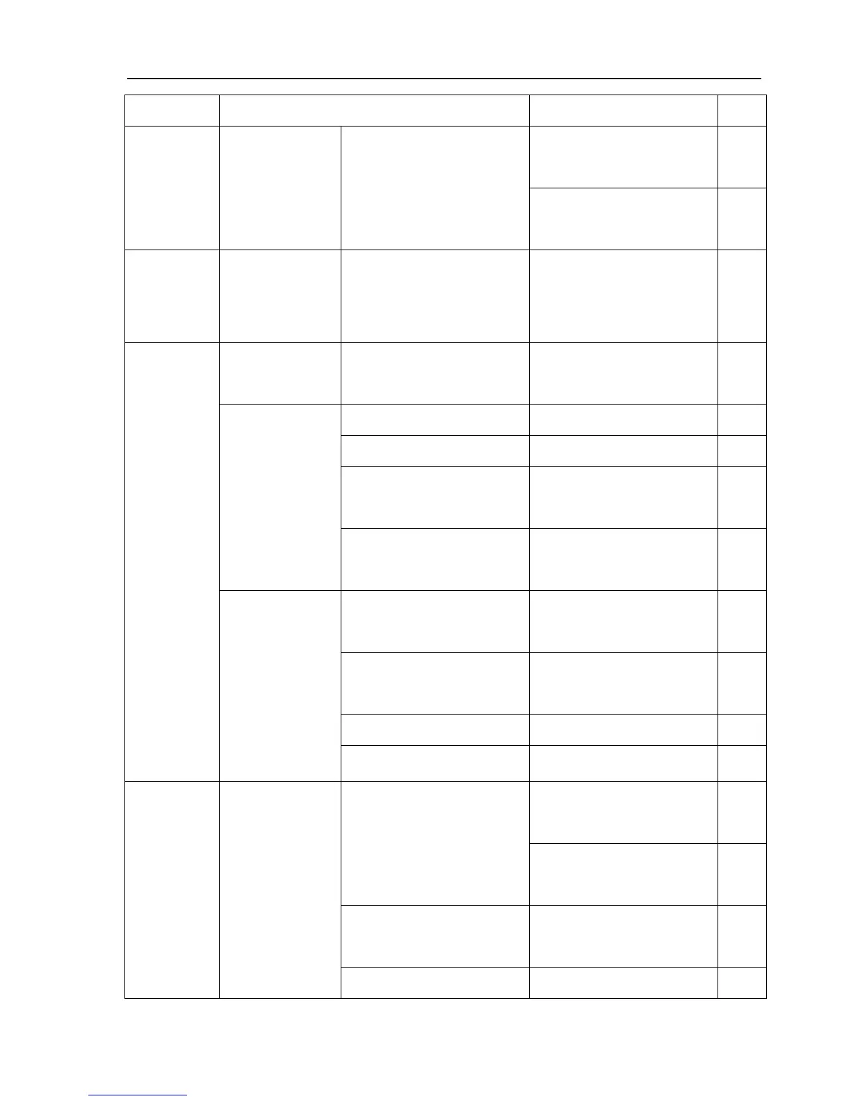
Component Specification Assembly Position Qty.
Upper End of the Left and
Right Steering Knuckle
2
GB/T3,452.1
O-Ring
30×3.55G
Both Ends of the Rocker
Shaft
2
Steering
Gear
GB/T9,877.1
Rotary Shaft Lip
Seal
B30×45×8 Steering Pitman Arm Shaft 1
JB/T2,600
Oil Seal
PD42×62×10 Lift Shaft 2
10×13.5 Oil Drain Plug 1
10×13.5 Cylinder Head 2
18×22
Position of the Hydraulic
Output Hollow Bolt
1
JB/T 982
Seal
36×42
Fuel Filling Breather
Assembly
1
71×2.65G
Cylinder Sleeve and
Housing Seal
1
17×2.65G
Cylinder Head Adjusting
Valve
1
53×5.3G Piston and Oil Cylinder 1
Lifter
GB/T3,452.1
O-Ring
53×5.3G Piston and Oil Cylinder 1
Handle Shaft, Safety Valve
Seat
1
9×2.65G
Junction Surface of the Lifter
Shell
1
13.2×2.65G
Impaction Screw Plunger of
the Safety Valve
1
Distributor
GB/T3,452.1
O-Ring
15×2.65G Junction Surface of the Lifter 1