Appendices
88
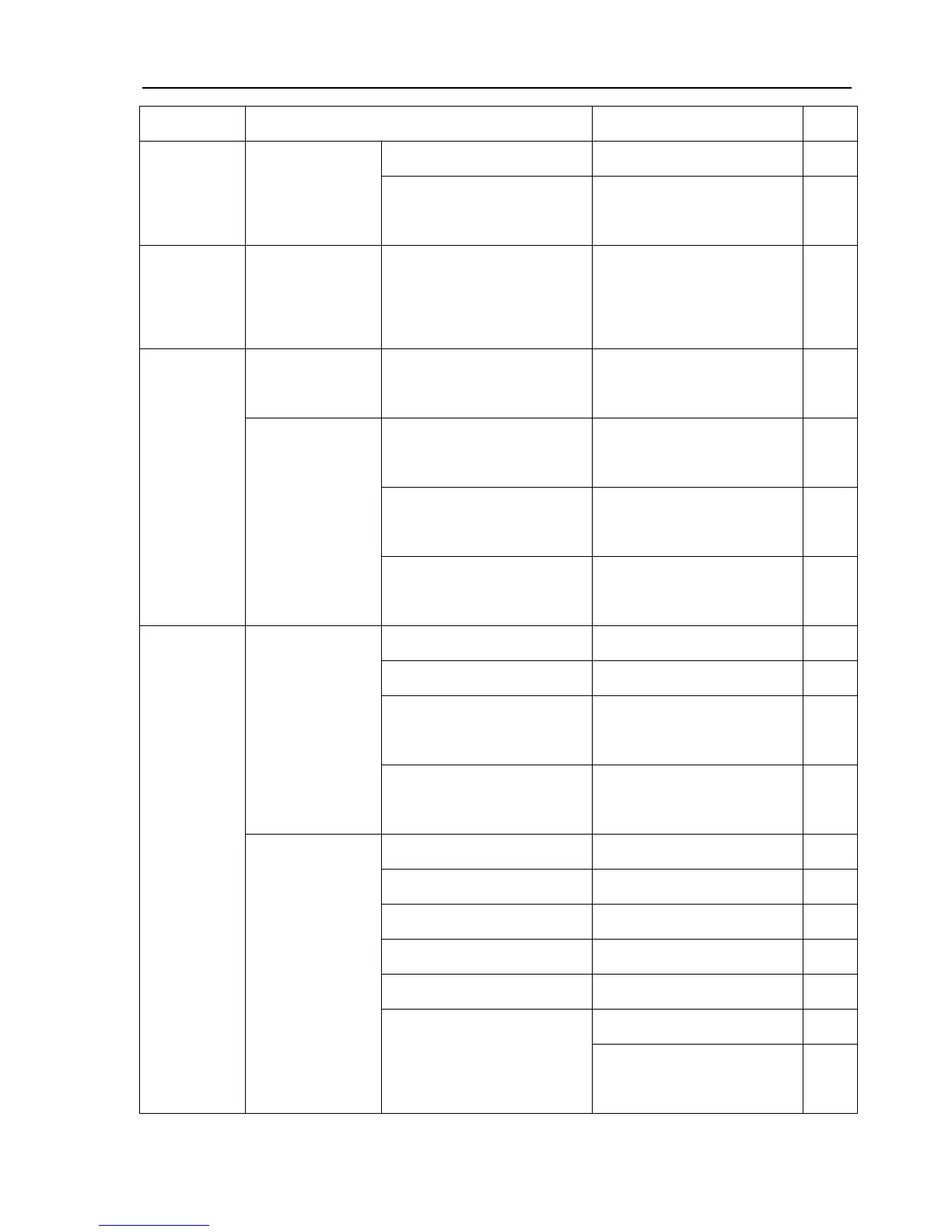
Component Specification Assembly Position Qty.
Shell
19×2.65G
Junction Surface of the Lifter
Shell
1
Oil Pump
and Oil
Passage
GB/T3,452.1
18×2.65G
O-Ring 18×2.65G
Suction Area of the Oil
Pump
1
JB/T2,600
Oil Seal
SG30×45×8
Output Shaft of the Transfer
Case
1
12.5×1.8G
Shifting Fork Shaft of the
Transfer Case
1
36.5×2.65G
Front of the Rear Jacket
Welding Parts
2
Transfer
Case
GB/T3,452.1
O-Ring
53×2.65G
Rear of the Rear Jacket
Welding Parts
1
PG45×65×10 Oil Sealing Retainer 2
SD45×70×10 Front Drive Shaft 2
SD50×70×12
Lower End of the Vertical
Shaft Sleeve
2
JB/T2600
JB/T2,600
Oil Seal
W50×72×7
Lower End of the Vertical
Shaft Sleeve
2
33.5×3.55G Master Pinion Shaft 2
34.5×3.55G Bearing Cover 2
40×3.55G Front Rocker Shaft 2
56×2.65G Dust Control Pipe Bracket 1
67×3.55G Front Rocker Shaft 2
Bearing Cover 2
Front Drive
Axle
GB/T 3452.1
GB/T 3452.1
O-Ring
75×2.65G
Outer End of the Half Axle
Sleeve
2