- 8 -
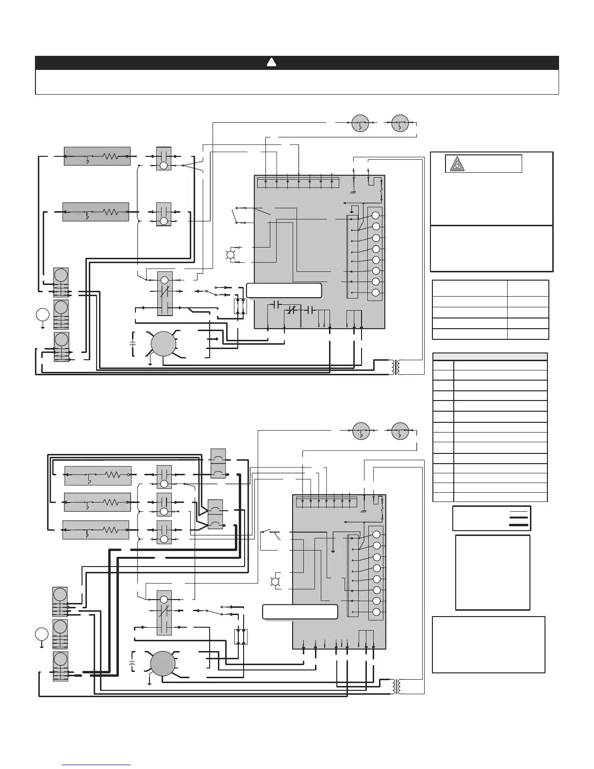
8. WIRING DIAGRAMS
!
WARNING
Risk of electric shock. Disconnect power before installation, servicing, maintenance or field wiring. Replace all panels
before operating. Failure to do so can result in electric shock causing severe injuries or death.
W
W
Open: 93.3°C
MRTP 1 MRTP 2
W
Y
Y
Y
Y
F1
5 AMPS
24 VAC
COMMON OUT
FUSED 24 VAC
POWER OUT
CALL FOR FAN
CALL FOR COOL
REVERSING VALVE
CALL FOR HEAT 1
CALL FOR HEAT 2
CALL FOR COOL 1
Class 2 Transformer
Pri: 240 V 60 Hz
Sec: 24 V 60 Hz 40 VA
T
R
BK
P1
Y1W2W1O
Y/Y2
GRC
Power
Heat 1
Heat 2
Heat 3
Heat 4
Vout
GND
1234567
P3
24VAC
BOARD POWER SUPPLY
BK
P2-8
P2-7
P2-6
P2-5
P2-4
P2-3
P2-2
P2-1
P2
GR
PP
10 kW 240 VAC
Single phase
HEAT
COOL
FAN
XFMR
VSPOWER
L2 COM
L2
R
O
BK
BK
O
K2
K2
K1
L1
L2 COM2
Heat Activation
HEAT INDICATOR
PP
PP
GR
PP
BK
LO
TB
Speed Selector
MED-HI
R
Y
BK
R
Y
Y (MED-LO)
R (LO)
BL (MED-HI)
BK (HI)
M
MED-HI
HI
MED-LO
LO
C
BR
BR
O
24V
DC
NC
BL
PK
5
1
2
4
3
6
W
W
K7
PK
GR
W
BK
R
L2
N
G
R
BK
L1
R
BK
BK
R
BK
BK
R
R
HEAT 1
E
ARTP
HEAT 2
E
ARTP
W
W
GR
BK
PK
PK
BK
NO
24V
DC
KC1
COM
HEAT 1
NO
24V
DC
KC2
COM
HEAT 2
W
W
Open: 93.3°C
MRTP 1 MRTP 2
W
Y
Y
Power
Heat 1
Heat 2
Heat 3
Heat 4
Vout
GND
1234567
P3
24VAC
BOARD POWER SUPPLY
PK
GR
W
BR
Y
Y
F1
5 AMPS
24 VAC
COMMON OUT
FUSED 24 VAC
POWER OUT
CALL FOR FAN
CALL FOR COOL
REVERSING VALVE
CALL FOR HEAT 1
CALL FOR HEAT 2
CALL FOR COOL 1
Class 2 Transformer
Pri: 240 V 60 Hz
Sec: 24 V 60 Hz 40 VA
T
R
BK
P1
Y1W2W1O
Y/Y2
GRC
BK
P2-8
P2-7
P2-6
P2-5
P2-4
P2-3
P2-2
P2-1
P2
GR
PP
15 kW 240 VAC
Single phase
BK
PP
GR
PP
PP
HEAT
COOL
FAN
XFMR
VSPOWER
L2 COM
L2
R
O
BK
BK
O
L1
L2 COM2
LO
TB
Speed Selector
MED-HI
R
Y
Heat Activation
HEAT
INDICATOR
Y (MED-LO)
R (LO)
BL (MED-HI)
BK (HI)
M
MED-HI
HI
MED-LO
LO
C
BR
BR
O
24V
DC
NC
PK
5
1
2
4
3
6
W
W
K7
Y
BL
BK
BK
BK
R
L2
N
G
R
L1
BK
BK
R
R
BK
BK
R
R
HEAT 1
E
ARTP
HEAT 2
E
ARTP
BK
R
HEAT 3
E
ARTP
W
GR
BK
NO
24V
DC
KC1
COM
HEAT 1
W
BR
BK
NO
24V
DC
KC2
COM
HEAT 2
W
P
BK
NO
24V
DC
KC3
COM
HEAT 3
PK
50 A
25 A
For the use of a two-stage
thermostat or an outdoor
thermostat, connect between
W1 and W2. Make sure that the
Heat Activation switch is set to
“Slow” position.
FE0065A
1. If any of the original wire, as supplied, must
be replaced, use the same equivalent wire.
Wiring must comply with applicable codes,
ordinances and regulations.
2. Field wiring must comply with applicable
codes, ordinances and regulations. Use only
Class 1 wiring inside furnace compartments.
Critical characteristic
Line voltage wiring:
UL AWM 1015, 600V, 105°C, VW-1, 8 AWG;
CSA TEW 600V, 105°C, FT1, 8 AWG and 12 AWG.
Low voltage wiring:
same ratings as high voltage except 18 AWG.
HI
MED-HIGH
MED-LOW
LOW
FAN MOTOR SPEED
BLACK
BLUE
YELLOW
RED
COLOR
LEGEND
C
E
KC
K
MRTP
HEAT
L1, L2
Capacitor
Heating Element
Heating Element Relay
Fan Relay
Auto-Reset Thermal Protector
Manual-Reset Thermal Protector
240 V Line Supply
ARTP
M
TB
T
N
Fan Motor
Terminal Block
Transformer Class 2
Heat
Neutral
F1 Fuse
Low power
High power
High power 8 AWG
B Breaker
WIRING COLOR CODE
BK BLACK
BL BLUE
BR BROWN
GR GREY
PK PINK
O ORANGE
PP PURPLE
R RED
W WHITE
Y YELLOW
B2
25 A
BK
BK
R
R
B1
50 A
BK
R
UL AWM 1015/1230, 600V, 105°C, VW-1, 12 AWG;
21D10 Model
21D15 Model