- 7 -
7. U SING OPTIONAL EQUIPMENT
7.1 TWO-STAGE OR OUTDOOR T HERMOSTAT
(The HEAT ACTIVATION switch must be in the SLOW position).
Follow the directions supplied with the two-stage or outdoor thermostat in conjunction with the furnace wiring diagram.
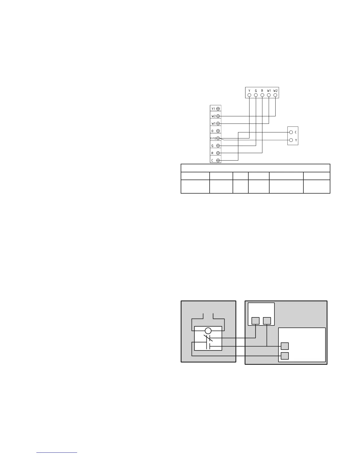
7.2 AIR CONDITIONING
Your furnace is equipped with all the controls required for the addition
of air conditioning (except the heat-cool thermostat).
The evaporator coil may be installed by a local contractor in sheet
metal plenum of his own manufacture. The coil should be located:
centred over the “chimney” of the furnace 4” (102 mm) to 6” (152 mm)
above the top of the furnace.
Make sure no air is allowed to bypass the cooling coil during cooling
operation. If the discharge opening is a great deal larger than the
coil, and the ductwork is correspondingly larger than the coil, you
may want to use a bypass damper for heating. The damper would be
closed in summer, directing all air flow through the coil. In winter the
damper would be open to allow air to bypass the coil.
Typical air-conditioning field wiring connections are shown in the
diagram at right.
FURNACE
THERMOSTAT
CONDENSE
FE0002A
WIRING COLOR CODE
CGRW1W2 Y
COMMON GREEN RED WHITE
WHITE (BLUE
OPTIONAL)
YELLOW
7.3 ELECTRONIC AIR CLEANERS AND/OR POWERED FURNACE HUMIDIFIERS
These units operate at 120 V. Your 240 V furnace is designed so that Model FK120 adaptor kit can be mounted inside the furnace to supply the
required 120 V. Instructions for mounting and wiring are included with the kit.
7.4 INTERLOCK CONNECTION
When the electric furnace is used in combination with another device
(as for example, a wood burning furnace), it is recommended to perform
the connection by referring to the wiring diagram at right. The burning
furnace thermostat will then turn automatically on the blower in the
electric furnace.
R
G
24 VAC
Power Output
Call for FAN
Furnace
Furnace
Thermostat
G
R
Relay
NC
NO
COM
External Request
for Fan Activation
FE0034A
Electric Furnace
System