Installation In a CAB-3 Series Cabinet
12 ACPS-2406 PN 51304:B 09/02/2003
Section 2 Installation
WARNING:High Voltages Present
Use extreme caution when working with the ACPS-2406. High voltage and AC line-connected
circuits are present in this power supply. Turn off and remove all power sources. To reduce
the risk of electric shock, make sure to properly ground the ACPS-2406.
Install the snap-on cover for TB1 after wiring.
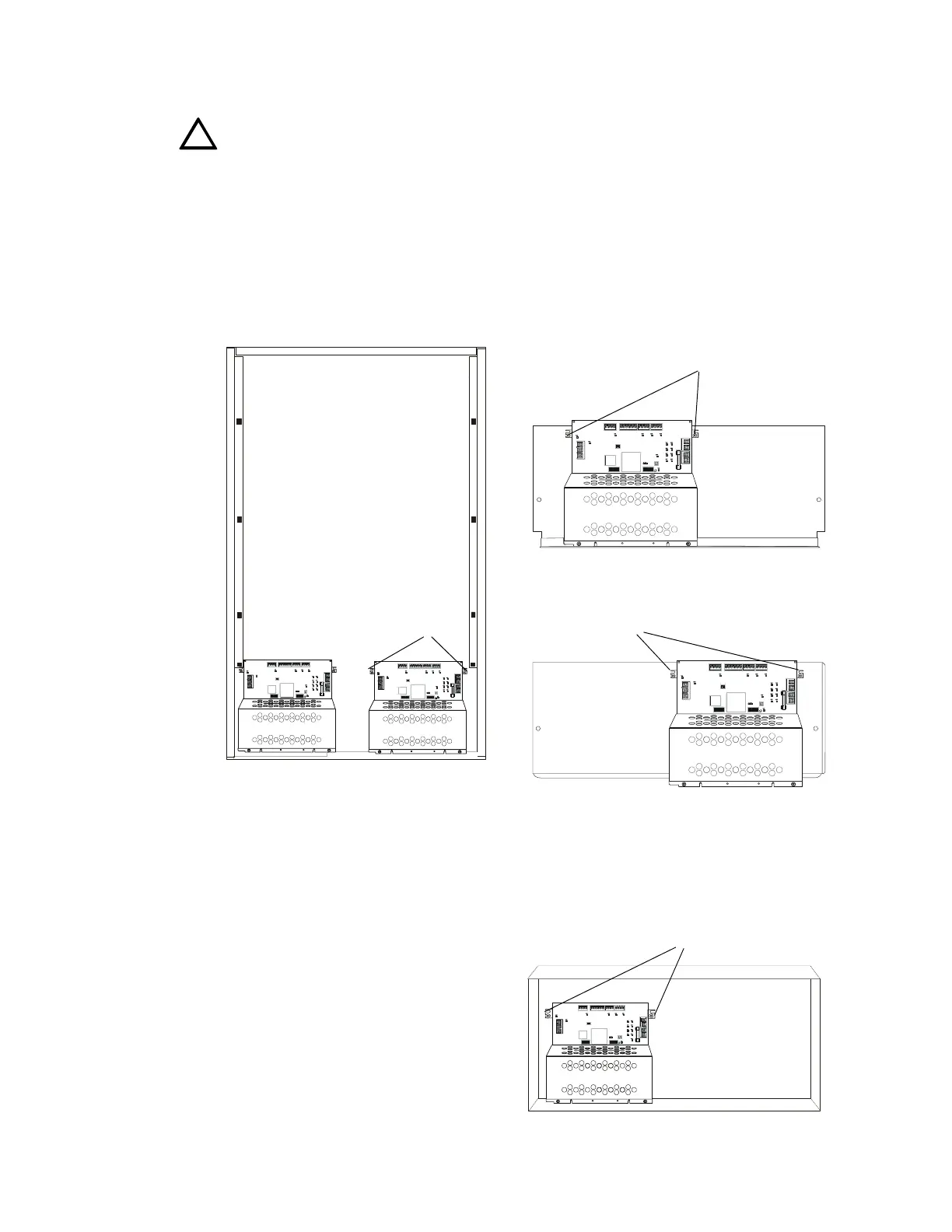
2.1 In a CAB-3 Series Cabinet
The ACPS-2406 mounts in the lower left or lower right of CAB-3 Series enclosure. It will also
mount in a CHS-6 chassis, requiring the left two of the three chassis spaces, or in a CHS-PS
chassis, where it must be installed in the right half.
Figure 2.1 Mounting in a CAB-3 Series Cabinet
2.2 In a BB-25 Cabinet
The ACPS-2406 mounts in the left side of a
BB-25 cabinet. Two 7 to 25 amp-hour
batteries fit into the right side of the cabinet.
!
D54
D73
HOT NEUTRAL EARTH
D74
D47
TB5TB6TB8
TB1
TB3
TB2
TB4
D40 D32
D66
OUTPUT 1 4 WIREOUTPUT 2 4 WIREOUTP UT 3OUTP UT 4
SUP+ SUP-
UZC
+24V COMM +24V RETUR N+24V COMM +24V RETURN
+24V COMM +24V COMM
SLCA SLCB
+ - + -
D67
F2
D68 D69
D70 D71
D72
D81
BATT IN B ATT O UT BATT IN BAT T O UT
OPTIONSOPTIONS
D75
+
+
__
8765432187654321
D54
D73
HOT NEUTRAL EARTH
D74
D47
TB5TB 6TB8
TB1
TB3
TB2
TB4
D40 D3 2
D66
OUTPUT 1 4 WIREOUTPUT 2 4 WIREOUTPUT 3OU TPU T 4
SUP+ SUP-
UZC
+24V COMM +24V RETUR N+24V COMM +24V RETURN
+24V COMM +24V COMM
SLCA SLCB
+ - + -
D67
F2
D68 D69
D70 D71
D72
D81
BATT IN BAT T OU T BATT I N BAT T O UT
OPTIONSOPTIONS
D75
+
+
__
8765432187654321
D54
D73
HOT NEUTRAL EARTH
D74
D47
TB5TB6TB8
TB1
TB3
TB2
TB4
D40 D32
D66
OU TP UT 1 4 WIREOUT P UT 2 4 WIREOUTPUT 3OUTPUT 4
SUP + SUP-
UZC
+24V COMM +24V RETURN
+24V COMM +24 V RE TURN+24V COMM +24V COMM
SLC A SLCB
+ - + -
D67
F2
D68 D69
D70 D71
D72
D81
BA T T IN B A TT O UT B A T T I N B AT T O U T
OPTIONSOPTIONS
D75
+
+
__
876543218765432 1
D54
D73
HOT NE UTR AL EA RT H
D74
D47
TB5TB6TB8
TB1
TB3
TB2
TB4
D40 D32
D66
OUT PU T 1 4 WIREOUT PUT 2 4 WIREOUT PUT 3OU TP UT 4
SUP+ SU P-
UZC
+24V COMM +24 V RE TURN
+24V COM M +24 V R E TU RN+24V COM M +24 V CO M M
SLCA SLCB
+ - + -
D67
F2
D68 D69
D70 D71
D72
D81
BATT IN BA TT O UT B ATT IN BATT O UT
OPTIONSOPTIONS
D75
+
+
__
876 543 2187 6543 21
Fasten the power
supply to the chassis
with hex nuts at these
positions
CHS-6 Chassis
CHS-PS Chassis
Fasten the power
supply to the chassis
with hex nuts at these
positions
CAB-3 Series Cabinet
The ACPS-2406 can fit in either
the lower left or lower right of
any CAB-3 Series cabinet.
Lower left
installation:
Slide the
power supply
chassis onto
the raised
cutouts on the
backbox
Lower right
installation:
Fasten the
power supply
to the backbox
with thread-
forming
screws.
acps6cab3.CDR
acps6chsps.CDR acps6chs6.CDR
D54
D73
D74
F2
OPTIONSOPTIONS
8765432187654321
Figure 2.2 Mounting in a BB-25 Cabinet
Fasten the power supply to the backbox
with screws (self-threading) at these
positions.
acps6bb25.CDR