Configuring the ACPS-2406 Addressing
20 ACPS-2406 PN 51304:B 09/02/2003
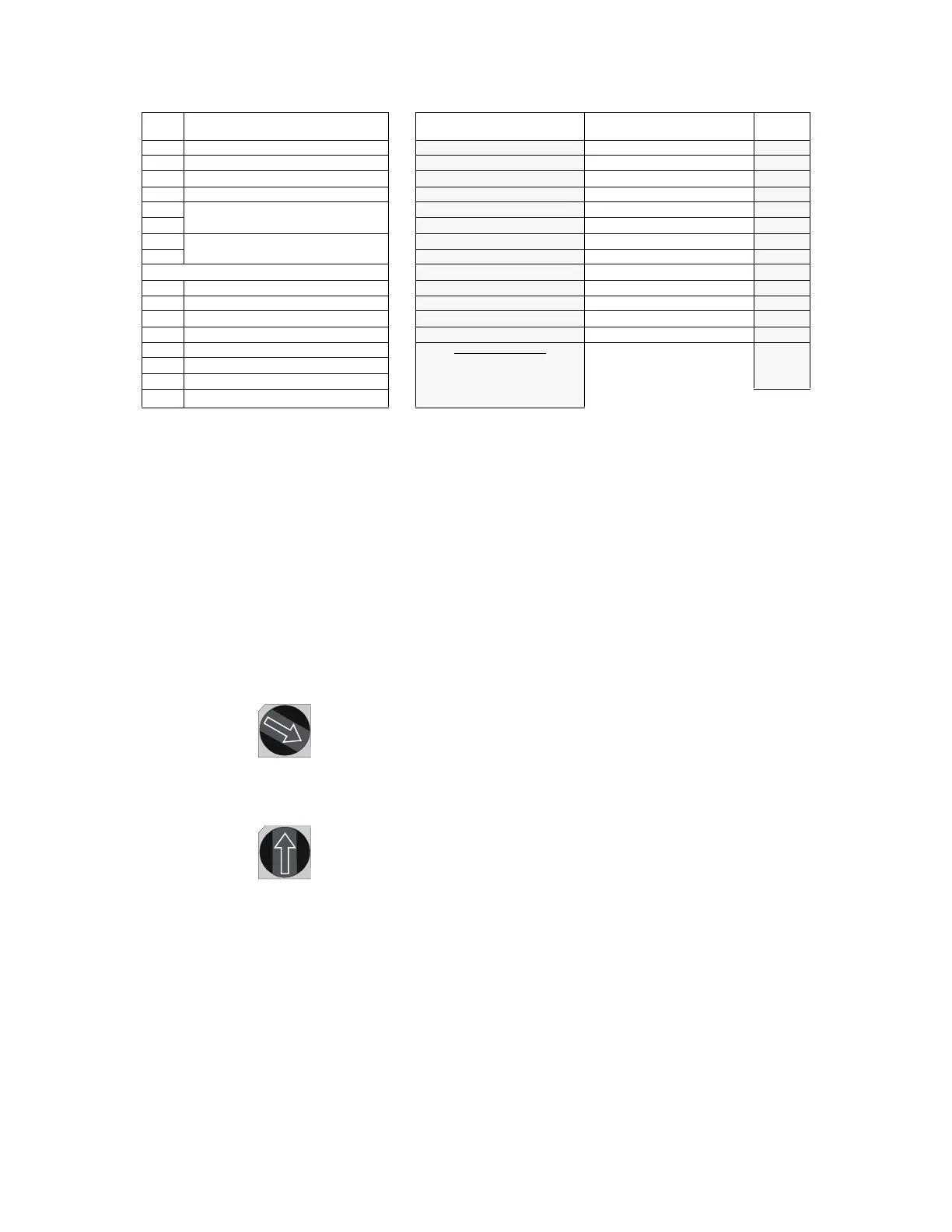
Table 3.7 DIP Switch Settings Resulting in 13 Addresses Consumed
Setting the Base Address
The combined rotary switch (SW1) and address jumper (JP6) settings select the base address, the
first address of the block of SLC addresses used. The address block will begin at a number that
ends in zero or five depending on the settings, and extend beyond that number to fulfill the
ACPS-2406 address requirements. All addresses included in the address block must be
programmed points at the FACP whether or not the output points are actually used.
Note: The lowest base address for the ACPS-2406 is 05. Do not set the FACP addresses 00 through 04 for the ACPS-2406.
The Rotary Switch
The rotary switch SW1 determines the address decade. Each number on the dial represents the ten
addresses of a decade. Turning the arrow until it points at a number selects that number’s decade.
For example:
Pointing the arrow at the 1 selects the “one” address decade, beginning at 10.
Pointing the arrow at the 12 selects the “twelve” address decade, beginning at 120.
JP6
The three pins of JP6 are used in conjunction with a shunt plug to further define the addresses.
They select the number that ends with zero or five in the decade defined by the rotary switch.
Placing the shunt plug over the two pins closest to the 0 selects the number with zero at the end as
the first address. Placing the shunt plug over the two pins closest to the 5 selects the number with
five at the end as the first address.
DIP
Switch
DIP Switch Setting
ACPS-2406 Addresses Selected
by DIP Switch Settings at Left
ACPS-2406 Addresses
SLC
Address
SW3.1 ON or OFF
✔ 1.Monitor General B*
SW3.2 ON or OFF
✔ 2. ACPS-2406 Output #1 B + 1
SW3.3 ON or OFF
✔ 3. ACPS-2406 Output #2 B + 2
SW3.4 ON or OFF
✔ 4. ACPS-2406 Output #3 B + 3
SW3.5
3.5 ON, 3.6 ON (Canadian Trouble
Reporting)
✔ 5. ACPS-2406 Output #4 B + 4
SW3.6
✔ 6. Signal Silence Address B + 5
SW3.7
3.7 ON, 3.8 OFF (Dual Stage)
✔ 7. Monitor AC Fail (Canada only) B + 6
SW3.8
✔ 8. Monitor Battery (Canada only) B + 7
✔ 9. Monitor Earth Fault (Canada only) B + 8
SW2.1 ON or OFF
✔ 10. Dual Stage Output #1 B + 9
SW2.2 ON or OFF
✔ 11. Dual Stage Output #2 B + 10
SW2.3 ON or OFF
✔ 12. Dual Stage Output #3 B + 11
SW2.4 ON or OFF
✔ 13. Dual Stage Output #4 B + 12
SW2.5 ON
Total:13 Addresses
Assign 13 sequential SLC
addresses for this DIP Switch
configuration.
*B =SLC
Base
Address
SW2.6 ON or OFF
SW2.7 ON or OFF
SW2.8 ON or OFF
S1W
1
0
5
7
8
62
3
4
9
11
10
14
12
13
15
S1W
1
0
5
7
8
62
3
4
9
11
10
14
12
13
15
rotarysw.CDR