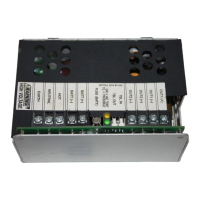
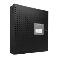
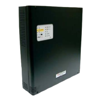
Features Introduction
ACPS-2406 PN 51304:B 09/02/2003 7
Section 1 Introduction
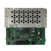
The ACPS-2406 is an auxiliary addressable power supply and battery charger with 24 VDC
outputs. It operates in FlashScan® or CLIP (Classic Interface Protocol) mode, and has built-in
strobe synchronization. It may be configured to drive four Notification Appliance Circuits or,
alternately, may be configured to provide four-wire detector power or general purpose power.
1.1 Features
• Addressable by any FlashScan® or CLIP FACP (Fire Alarm Control Panel)
• Strobe/NAC Synchronization with System Sensor SpectrAlert™* Series horns and strobes, or
Gentex or Wheelock horns and strobes. (Use only devices from the same manufacturer in each
system).
*SpectrAlert is a registered trademark of System Sensor
• NAC synchronization with UZC-256 (Universal Zone Coder)
• Provides four coded or non-coded NACs that share 6.0 A of output power, or, configured
differently, will supply 5.0 A of four-wire detector power or general purpose power
• Power-limited outputs
• Charges 7 to 25 AH batteries
• Auxiliary +24 VDC @ 0.5 A output for use within the same cabinet
• Isolated Signaling Line Circuit (SLC) interface
• Brownout detection
• Battery/battery charger supervision
• AC loss detection and AC loss delay reporting
• Selectable Ground Fault Detection
• Occupies between five and 13 addresses on an SLC, depending on configuration
• Canadian Two-stage with Temporal Pattern for Evacuation
1.2 Specifications
• Primary (AC) Power - TB1
• ACPS-2406 - 110-120 VAC 50/60 Hz input, 2.7 A maximum
24 VDC output voltage regulated and power-limited
• Output Circuits - TB4, TB5, TB6
• 2.5 A maximum for any one output circuit
• 5.0 A (continuous), 6.0 A during an alarm (1 hour UL rating)
• Auxiliary Power Output - J1 - 24 VDC @ 0.5 A, for use within the same cabinet. When this
output is used for an installation, the maximum load current available at Output #4 (TB6-3 and
TB6-4) will become 2.0 A maximum.
• Secondary Power (Battery) Charging Circuit - TB2, TB3 - lead-acid battery charger which
will charge 7 to 25 AH batteries. Maximum charger current - 1.1 A
• Wheelock synchronization devices are compatible with ACPS-2406 software greater than
#ACPS1.3, together with Revision L or higher of the ACPS-2406 PC board. (Figure 1.1 on
page 10 for revision location.)


 To Next Page