Introduction Board Layout
10 ACPS-2406 PN 51304:B 09/02/2003
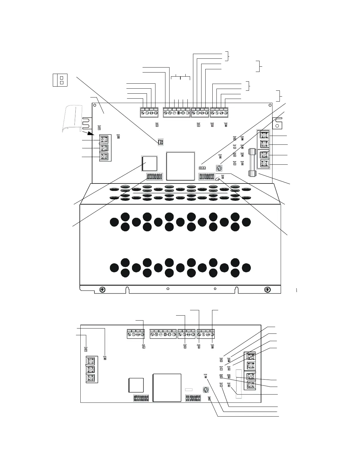
Figure 1.1 The ACPS-2406 Board Layout
D54
D73
HOT NEUTRAL EARTH
D74
D47
TB5TB6TB8
TB1
TB3
TB2
TB4
D40 D32
D66
OU TPUT 1 4 WI RE
OU TPUT 2 4 WIR E
OUTPUT 3OUTPUT 4
SUP+ SUP-
UZC
+24 V CO MM +24 V RE TU RN+24 V CO MM +24 V RE TU RN
+24 V CO MM +24V CO MM
SLCA SLCB
+ - + -
D67
F2
D68 D69
D70 D71
D72
D81
BATT IN BATT OUT BATT IN BATT OUT
OPTIONSOPTIONS
D75
+
+
__
87654 32187654321
ACPS-2406PCA
Rev _____
D54
D73
D74
D47
D40 D32
D66 D67
F2
D68 D69
D70 D71
D72
D81
OPTIONSOPTIONS
D75
8 765 432 187654321
C
A
U
T
I
O
N
!
H
I
G
H
V
O
L
T
AG
E
JP2 - Ground Fault
Disable - Cut this
jumper to disable
ground fault
detection.
Auxiliary Power
Supply
Rotary Switch
JP6
AC
SLC A
SLC B
-
-
+
+
UZCSUP
+
-
NEUT
EARTH GROUND
BAT OUT
+
-
+
-
BAT OUT
BAT IN
BAT IN
+
Output 1
NAC 1
NAC 2
NAC 3
NAC 4
Locations of LED Indicators
Refer to Table 1.2 for
Indicator Descriptions
TRBL (Pulse-coded)
BAT/CHG
UC FAILURE
AC
GROUND FAULT
NAC 1 Activated
NAC 2 Activated
NAC 3 Activated
NAC 4 Activated
SLCTXA
SLCRXA
Battery Fuse
-
+
-
+
Output 2
-
+
-
+ OUT 4
-OUT 4
+OUT 3
-OUT 3
MONITOR
Flash Memory
SW2 DIP
Switches
SW3 DIP
Switches
Output 4
Output 3
Snap-on
cover for
TB1
terminals
Out 1
Out 1 4-Wire
Out 1 4-Wire
Out 2
Out 2 4-Wire
Out 2 4-Wire
UZCSUPRET
Class A
Class A
Refer to Figure
3.1 and Table 3.1
Refer to Figure
3.1 and Table 3.1
acps6cplt.CDR
acps6brdtop.CDR
J1
+
-
1
{
Coded input
(UZC or
synch. signal)
ACPS-2406PCA revision #
(handwritten on board)