In a CAB-PS1 Cabinet Installation
ACPS-2406 PN 51304:B 09/02/2003 13
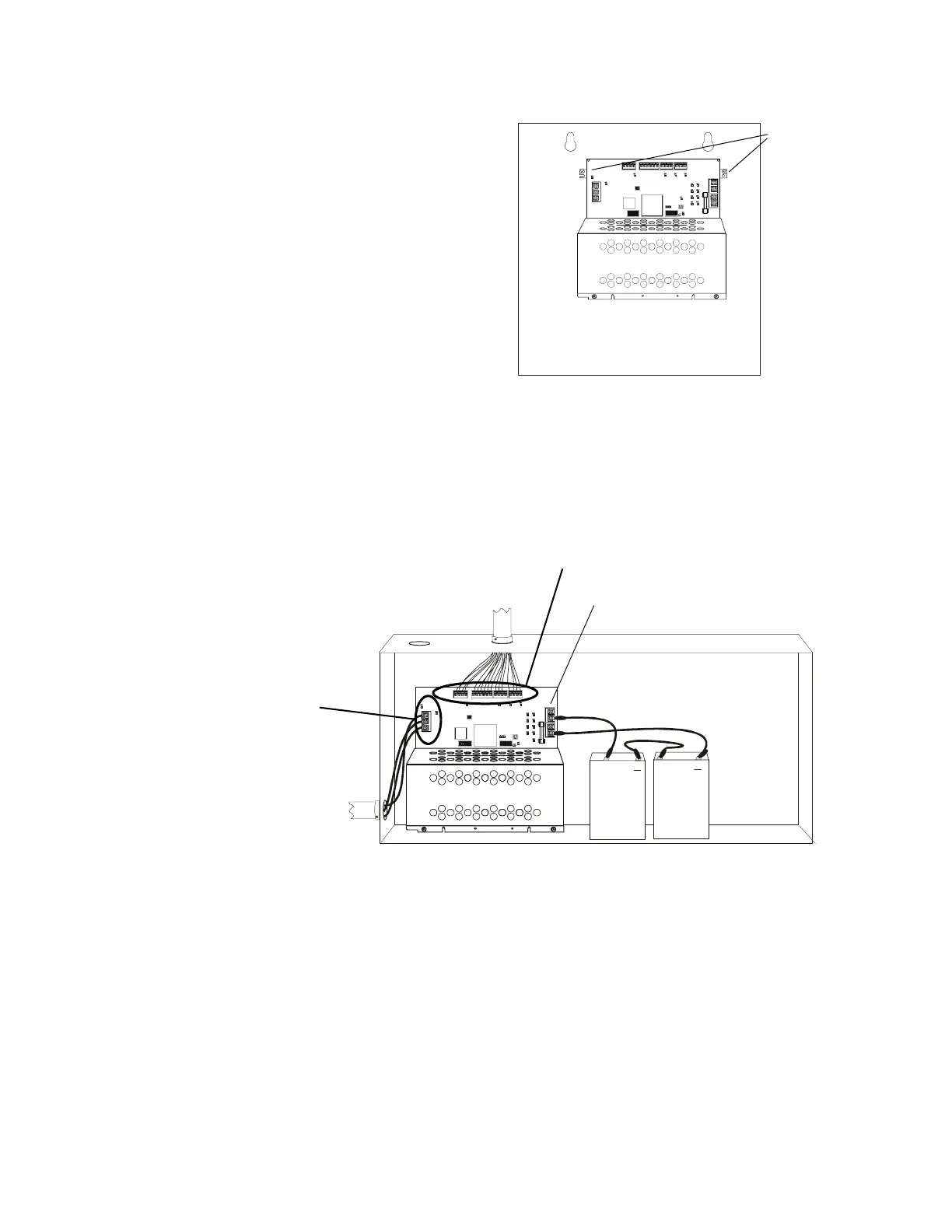
2.3 In a CAB-PS1 Cabinet
The ACPS-2406 mounts in a CAB-PS1
cabinet. Two seven amp-hour batteries fit
into the bottom of this cabinet along with the
ACPS-2406. The chassis is fastened to the
two top right studs with two hex nuts.
2.4 Wiring
The terminal block and pin connections are illustrated in Figure 1.1.
Power-limited wiring must remain separated from nonpower-limited wiring by at least 0.25 in.
(6.4 mm), and must enter an enclosure through different knockouts. Samples for configuring
power-limited and nonpower-limited wiring in three different cabinets are shown in Figure 2.4,
Figure 2.5, and Figure 2.6.
Figure 2.4 BB-25 Cabinet: Power-limited Wiring Example, with Two Battery Wiring
D54
D73
HOT NEUTRAL EARTH
D74
D47
TB5TB6TB8
TB1
TB3
TB2
TB4
D40 D32
D66
OUTPUT 1 4 WIRE
OUTPUT 2 4 WIREOUTPUT 3OUTPUT 4
SUP+ SUP-
UZC
+24V COMM +24V RETURN+24V COMM +24V RETURN
+24V COMM +24V COMM
SLCA SLCB
+ - + -
D67
F2
D68 D69
D70 D71
D72
D81
BATT IN BATT OUT BATT IN BATT OUT
OPTIONSOPTIONS
D75
+
+
__
87654 3218765432 1
Fasten the
ACPS-2406
chassis to the
backbox
using the
studs with
hex nuts at
these
positions.
Figure 2.3 CAB-PS1 Mounting
acps6cabps1.CDR
D54
D73
D74
+24V COMM +24V R ETURN+24V COMM +24V RETURN + - + -
F2
OPTIONSOPTIONS
8765432187654321
+
+
TB1: AC Primary
Power Wiring -
nonpower-limited
and supervised.
Output Circuit Wiring - Power-limited
Supervised except for TB6: UZCSUP+, UZCSUPRET-
acps6pwrlmtd.CDR
TB2: Non power-limited and supervised