NFS-320/E/C Installation Manual — P/N 52745:M2 7/1/14 21
Installing Option Boards Installation
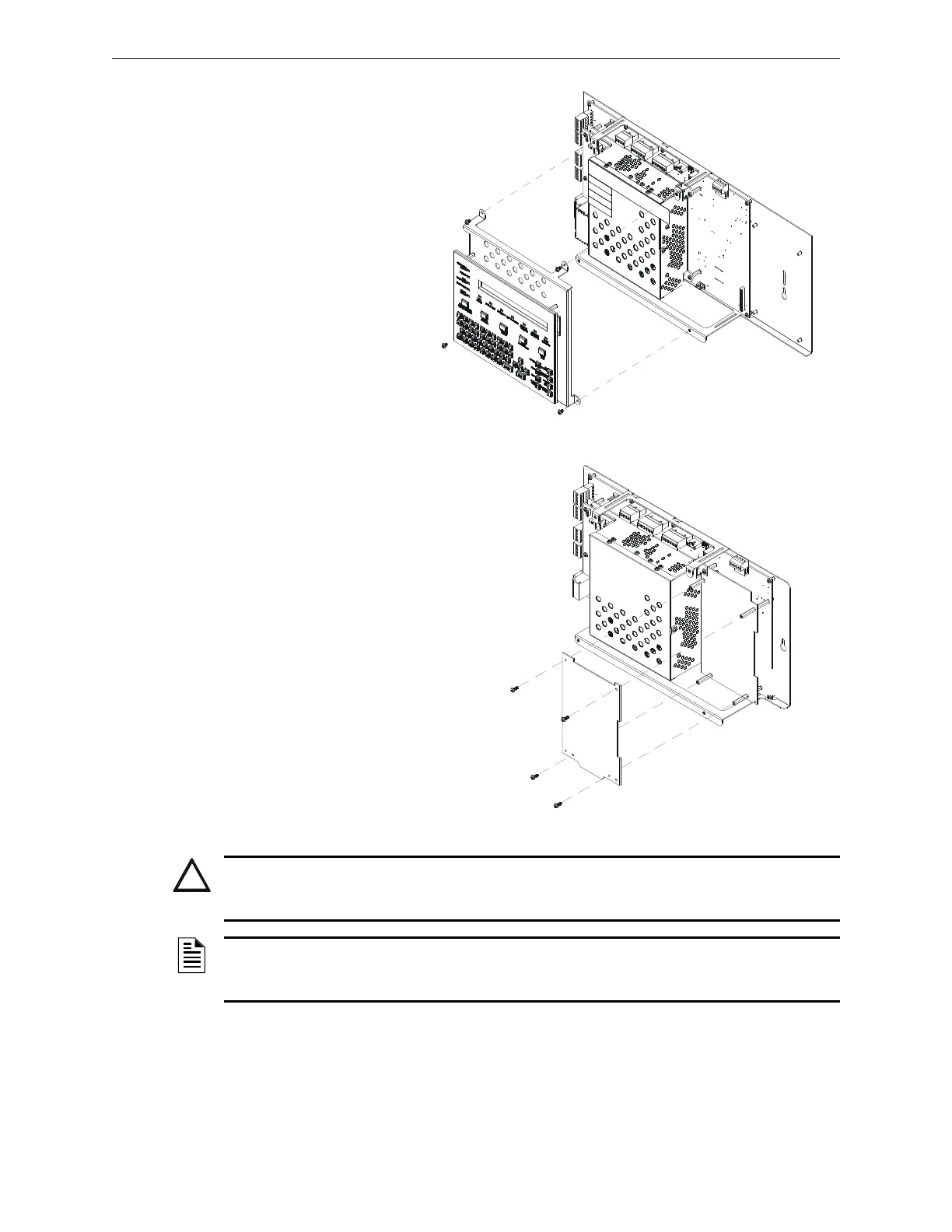
1. Remove and re-install
KDM-R2 as shown in
Figure 3.2. It may be
convenient to do some
basic field-wiring before
reinstalling KDM-R2.
2. Lay the first option board
over the four stand-offs
already installed on the
CPU, so that the holes and
stand-offs align.
3. If attaching a second
option board, use its standoffs to
secure the first option board, then lay
the second option board over the
standoffs. Two sizes of standoffs are
shipped with the option boards; select
standoffs that allow sufficient
clearance for electronics on the lower
option board.
4. Secure the top option board with four
#4-40 screws (supplied).
5. Re-attach KDM-R2.
Installing a Transmitter Module TM-4
TM-4 is power-limited. Connections are on TB10 nonresettable output and TB11 EIA-485 ACS
Mode. Refer to the Transmitter Module TM-4 installation document for installation details.
Figure 3.2 Removing and Reinstalling KDM-R2
320_assembly_tech_pubs_5-2.wmf
Figure 3.3 Installing Option Boards
320_assembly_tech_pubs_3-2.wmf
CAUTION:
It is critical that all mounting holes of the NFS-320/E/C are secured with a screw or standoff to insure
continuity of Earth Ground.
NOTE: It may be convenient to field-wire the SLC loop before installing any option boards, and
to make wiring connections on the first option board before installing a second option board in
front of it.
 Loading...


