15
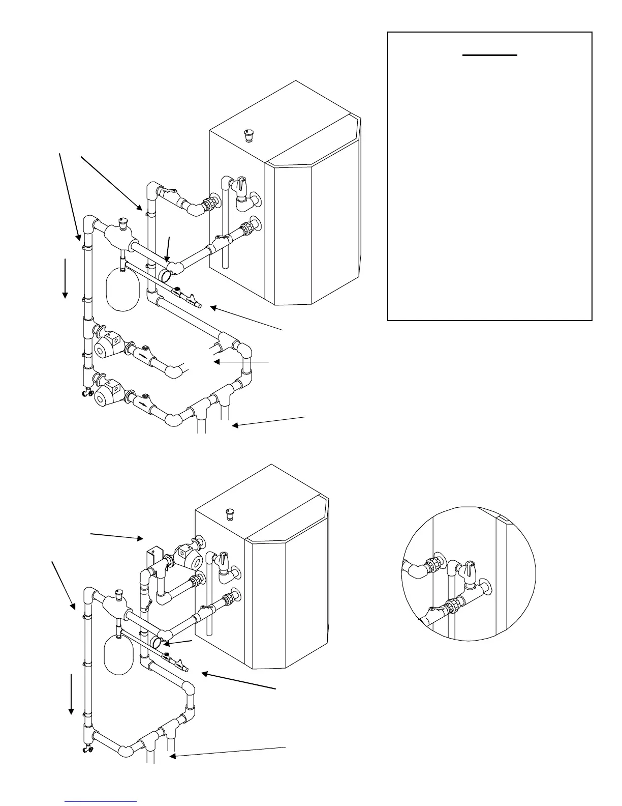
Legend
A- Back flow preventor
B- Fill valve (set at 12 psi)
C- Diaphragm expansion tank
D- Cast Iron Air scoop, for excessive air
use Spirovent (see page 12).
E- Automatic air vent
F- Relief valve (set at 30 psi)
G- Pressure gauge
H- Heating pump (see size
recommendations in Sec.6.1) Wired to
terminals C
1
- L
2
I- Optional Indirect pump (see
recommendations in Sec.6.1) Wired to
terminals A
p
- L
2
J- Optional Indirect Water heater
K- Swing check valve.
L- Ball Valve
M- Boiler Drain
N- Boiler inlet connection (warm)
O- Boiler outlet connection (hot)
P- External Combi Manifold #82470-1
Models Ti100-400ASME
O
Relief valve
location. All
other piping is
same as Ti150
Quantity and location of shutoff valves, and drains, are
at the discretion of the installer.
Primary Loop For Heating Model
Quantity and location of shutoff valves, and drains, are
at the discretion of the installed.
Ti 100-150
(
non ASME)
H
M
All piping
must be
secured to
wall for
support
Primary Boiler loop
F
L
E
C
B
Water
Supply
D
G
E
O
L
P
Insert secondary Loop here.
See page16-17
Primary Loop
For Combi Model Only
(Ti150C & Ti200C models only)
Primary Boiler loop
Optional Indirect (For installation
with Ti400, Indirect must have less then
16’ of head loss at 13usgpm.)
F
L
E
H
C
B
I
Water Supply
D
G
E
M
O
L
Insert Secondary-
Loop here.
See pages 16-17
All piping must
be secured to wall
for support