5
3.2 Venting Configurations
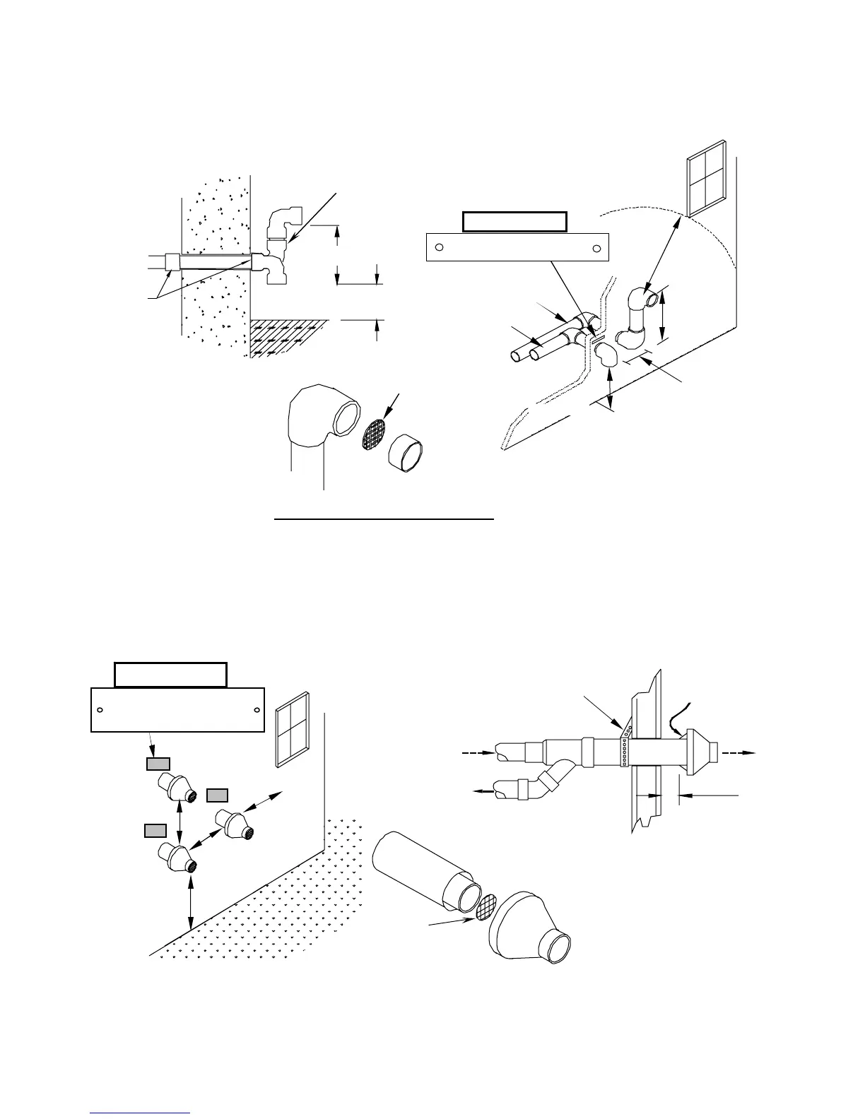
3.2.1 Two-Pipe Vent Termination
3.2.2 Concentric Vent Termination (No longer approved for Canada)
• Ti100-200 Only (Not for use with Ti400)
• NTI part number 82666 (York part number 1CT0303)
• Instructions included with vent terminal contain more detailed assembly and installation instructions.
• Clearances and requirements of this manual supersede those of the instructions included with the vent terminal.
• Terminal must be cemented together during installation.
12” Plus Snow allowance
Example 12+19=31”
Coupling and
elbow to be
against wall
– ½” play is
acce
table
18” Min
The vertical portion of the exhaust
termination does not require
insulation, if less than 5 feet in total
length
Must insert
plastic bird
r
n
Apply Plate
Gas Vent Directly Below
Kee
Free of Obstructions 36”
1
”
4”-12” or greater
than 36”
Outside Wall”
Exhaust
Intake
Window
12” Plus Snow
”
Must insert
plastic bird
screen
Must be 1”
from wall
Support
(Field installed)
Inlet
Exh
Inlet
Exh
Note: inlet pipe must always
be connected to the boiler.
36” min.
Minimum 12”
lus snow
allowance
4” or greater
than 24”
48” min.
Gas Vent Directly Below
Keep Free of Obstructions
l
Plate Here