Tx I&O Manual │DHW Piping (Combi)
Combi DHW Plumbing & Set-up
DHW Inlet & Outlet Connections – The Tx-Combi has two potable water connections, Inlet & Outlet, which
exit the bottom of the unit, nearest the back. The Inlet fitting is on the right and the Outlet fitting is on the left,
see Figure 11-1.
DHW Filter – Install the factory supplied Y-strainer prior to the inlet fitting, as illustrated in Figure 11-1. The
serviceable Y-strainer has a 100 micron filter and will protect the internals from damage caused by dirt and
debris.
Check Valve – The installation of a check valve in the hot water line is recommend to prevent expansion devises
downstream from back flowing when the water pressure drops during cold water draws. Failure to prevent the
backflow will cause a momentary forward flow of water through the flow sensor when the cold-water draw has
ended and the water pressure increases. This forward flow of water will momentarily activate DHW mode.
Throttling Valve – Use one of the isolation valves, installed hot water line, as a throttle valve to regulate the
maximum hot water flow rate. The Tx-Combi has a limited firing rate (151MBH for model Tx151C, 199MBH
for model Tx200C); therefore excessive flow rates will result in cooler hot water temperatures.
Drain and Isolation Valves – Install drain and isolation valves on the cold water inlet and hot water outlet lines,
as shown in Figures 11-1 and 11-2, to allow for servicing of the internal brazed plate heat exchanger and other
potable water components. It will be necessary to flush or clean the brazed plate heat exchanger, if it is exposed
to hard water.
Instantaneous DHW (without Storage Tank)
The Tx-Combi will provide domestic hot water continuously when flow is present. This method is the most
efficient means of heating water by allowing the boiler to operate at a lower return water temperature, thus
increasing combustion efficiency, and minimizing standby losses. See Figure 11-1 for installation details.
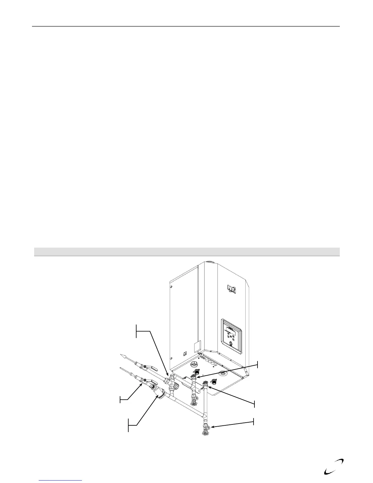
Figure 11-1 Near Boiler DHW Piping (Tx151C & Tx200C)
Tempering Valve
(Check local codes)
Y-Strainer
(Factory supplied)