Display Menu Guide │ Tx I&O Manual
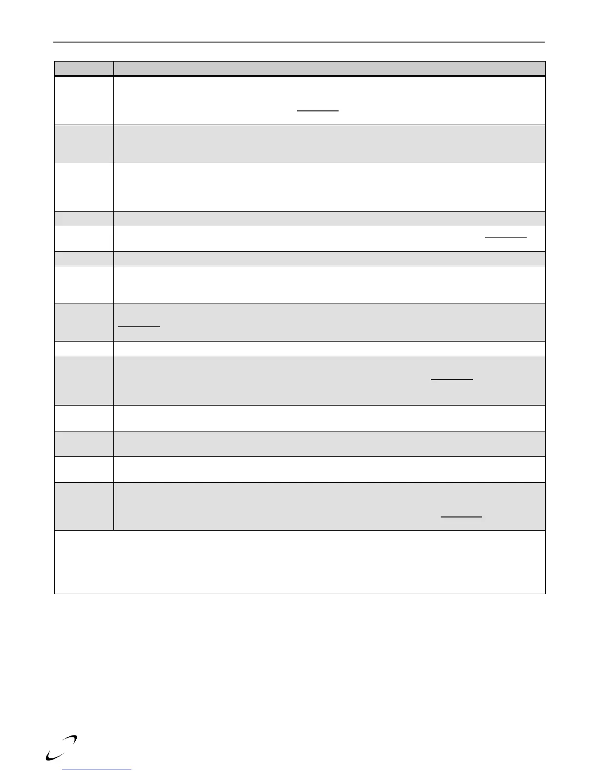
Table 17-1 User Menu
Current target temperature – displays the current target temperature of the boiler outlet sensor for the
active demand (DHW or Central Heating). For central heating with outdoor reset, the calculated central
heating target temperature will be displayed. NOTICE: model Tx-Combi models will display “---” during
DHW demands.
CH setpoint (at OD = 0⁰F) – displays the maximum central heat setpoint, set via Installer Menu setting 2-
01. Setting establishes the boiler operating temperature during central heat demands when the outdoor
temperature is 0⁰F or less.
DHW temperature – displays the temperature reading from; (i) the Tank sensor (NTI P/N: 84632) located
in an indirect water heater or (ii) the DHW sensor inside the Tx-Combi boiler (NTI P/N: 84907). When no
sensor is used, “OPEn” indicates an open circuit, and “CLOS” indicates a closed circuit – i.e. contact
closure from an indirect thermostat.
DHW setpoint – displays the DHW setpoint, set via Installer Menu setting 2-07.
DHW flow rate (gpm) – displays the DHW flow rate sensed at the Tx-Combi DHW sensor. NOTICE:
when the sensor is disconnected, 0.49 is displayed.
Fan speed actual (rpm) – displays speed at which the combustion blower is operating.
Flame signal (µA) – displays the flame strength signal sensed from the ionization electrode, NTI P/N:
84740; minimum signal to sustain normal burner operation is 3µA. Burner operation is completely
prohibited when the signal drops below 1.5µA.
Outdoor sensor temperature – displays reading from outdoor temperature sensor, NTI P/N: 83604.
NOTICE: when sensor is open (not connected) display indicates -40⁰F/C or “OPEn”; when sensor is
shorted display indicates 176⁰F/80⁰C or “OPEn”.
Return sensor temperature – displays reading from boiler inlet temperature sensor, NTI P/N: 84745.
Flue sensor temperature – displays reading from boiler flue temperature sensor, NTI P/N: 84780. Burner
operation is inhibited when the flue temperature reading is in excess of 220⁰F. NOTICE: an open circuit
is displayed as 50⁰F/10⁰C and a blocking error “Err 78” occurs; a short circuit is displayed as 278⁰F/137⁰C
and a blocking error “Err 86” occurs.
Boiler pump – indicates the status (On/Off) of the Boiler Pump output. Note: the Boiler Pump output is on
during all demands.
Central heat pump – indicates the status (On/Off) of the CH Pump output. Note: the CH Pump output is
on during central heat demands; the CH Pump will turn off during priority DHW demands.
DHW pump – indicates the status (On/Off) of the DHW Pump output. Note: the DHW Pump output is on
during priority DHW demands.
System sensor temperature – for use only in cascade systems, displays reading from a system temperature
sensor, NTI P/N: 84010. When used, the system sensor is only wired to the managing boiler, i.e. boiler
with S4 switch set to on, and boiler address (Installer Menu setting 2-20) set to 1. NOTICE: an open
circuit is displayed as “OPEn”; a short circuit is displayed as “CLOS”.
Notes:
1
Enter User Menu by pressing the UP or DOWN button; to scroll through menu options, continue pressing the UP or
DOWN button.
2
Exit User Menu by pressing the OK button.
3
User Menu is for viewing only; to adjust settings refer to the Installer Menu.