79
TRX Series II - Installation - Startup - Maintenance Instructions
Building Management System.
Only visible with 0-10V / 4-20mA Clip-In Board installed
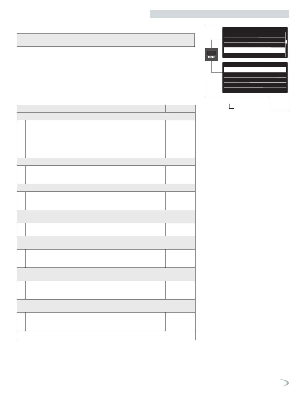
To navigate the BMS Control menu proceed as follows:
1. From the Tech Menu, turn the dial to highlight “BMS Control” and press ENTER.
2. Scroll to the parameter to be adjusted/viewed and press ENTER.
Note: most parameter options will only be visible after setting Control Mode ≠ 0, and after
exiting and reentering the BMS Control menu.
3. Modify the setting by turning the dial, press ENTER to save the value.
Note: pressing ESC exits the screen without saving the new value.
4. Press ESC to return to the previous screen.
DHW setup
Cascade Setup
Restore/Backup
BMS Control
Complete Menu
BMS Controls
Control mode
Max Temperature
Min Temperature
Control Signal to Start Heat Demand
Control current - start heat Demand
Tech Menu
DHW setup
Cascade Setup
Restore/Backup
BMS Control
Complete Menu
BMS Controls
Control mode
Max Temperature
Min Temperature
Control Signal to Start Heat Demand
Control current - start heat Demand
5. BMS Controls
Figure 96 - Tech Menu
BMS Control
Table 37 - Tech Menu - BMS Controls Menu
Menu Option | Description (Range) Default
CONTROL MODE (42.0.0)
Disabled (0) – the boiler maintains control of the burner power and setpoint
temperature.
0-10V (Power or Temp) (1 or 2) – the boiler power level, or setpoint
temperature, is modulated proportionally to the 0-10V input signal.
Current (Power or Temp) (3 or 4) – the boiler power level, or setpoint
temperature, is modulated proportionally to the 4-20mA input signal.
Disabled
MAX TEMPERATURE (42.0.1)
Sets the maximum boiler temperature, corresponding to an input signal equal to
the Max Control Signal, when Control Mode = 2 or 4. (Range = Min Temperature
to 179°F)
179°F
MIN TEMPERATURE (42.0.2)
Sets the minimum boiler temperature, corresponding to an input signal equal to
the Min Control Signal, when Control Mode = 1 or 3. (Range = 68°F to Max
Temperature)
68°F
CONTROL SIGNAL TO START HEAT DEMAND (42.1.0) / CONTROL CURRENT
– START HEAT DEMAND (42.1.4)
Sets the minimum input control signal required to start a heat demand. (Range =
Control Signal to Stop Heat Demand to Min Control Signal)
1.0V / 4mA
CONTROL SIGNAL TO STOP HEAT DEMAND (42.1.1) / CONTROL CURRENT –
STOP HEAT DEMAND (42.1.5)
Sets the control signal that correlates to the Max Temperature if Control Mode = 2
or 4, or max burner power if Control Mode = 1 or 3. (Range = Min Control Signal
to 10.0V/20mA)
0.5V / 2mA
MAX CONTROL SIGNAL (42.1.2) /CONTROL CURRENT – MAXIMUM DEMAND
(42.1.6)
Sets the control signal that correlates to the Max Temperature if Control Mode =
2 or 4, or max burner power if Control Mode = 1 or 3. (Range = Min Control
Signal to 10.0V/20mA)
10.0V /
20mA
MIN CONTROL SIGNAL (42.1.3) /CONTROL CURRENT – MINIMUM DEMAND
(42.1.7)
Sets the control signal that correlates to the Min Temperature if Control Mode = 2
or 4, or min burner power if Control Mode = 1 or 3. (Range = Control Signal to
Start Heat Demand to Max Control Signal)
2.0V / 4mA
Part 9 - Controls
 Loading...


