96
420012001500 - 03182024 - Rev. 04
Part 11 - Start-Up
B. Combustion Checking Procedure
The order of operations for this procedure must always be respected.
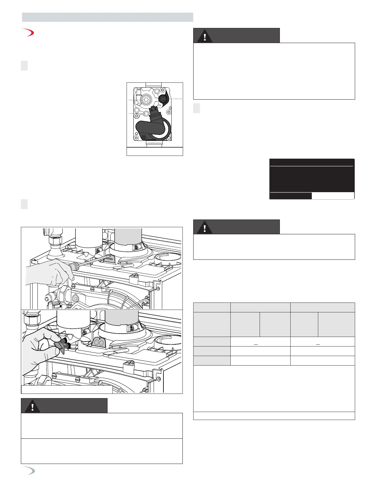
OPERATION 1
GAS INLET PRESSURE CHECK
Loosen screw 1 (Torx 10 - Line Pressure Test Port) and connect a
manometer to the port using applicable
tubing.
Ensure the boiler is powered on.
Enable Burner Test - access the Main Menu
by pressing the Menu button.
Turn the dial to select Test Mode and press
ENTER. Press ENTER to activate Burner Test.
Turn the dial to select MAX Power and press
ENTER.
The boiler turns on at maximum power.
The gas line pressure must remain within
the range provided in Table 43 for the gas
type during all operating conditions.
Upon completion of the combustion analysis and adjustment
(Operations 2 through 5), remove the pressure gauge and tighten
screw 1.
VERIFY AND REPAIR ANY GAS LEAKS.
4
2
1
Figure 105 - Gas Valve
Figure 106 - Combustion Test Port
Make sure the calibrated combustion analyzer is set to the appropriate
gas type. Failure to do so could result in serious personal injury or
death.
WARNING
WARNING
It is required to use a calibrated combustion analyzer to verify final
adjustment according to the combustion chart (Table 43). Failure to
do so could result in serious personal injury or death.
WARNING! When the Burner Test Function is activated the
temperature of the water coming out of the boiler may exceed
179°F.
WARNING
It is very important that the combustion system be set within the
recommended CO measurements listed in Table 43. Visually
looking at the burner does not determine combustion quality.
Failure to measure combustion with a calibrated combustion
analyzer and set the throttle within the recommended CO
measurements could result in property damage, severe
personal injury, or death.
OPERATION 3
CHECKING THE CO2 AT MAX POWER (100%)
Set the thermostat at the highest possible setting or draw off the
domestic hot water at the maximum water flow rate to create a
demand for heat.
Enable Burner Test, access the Main Menu by pressing the Menu
button.
Turn the dial to select Test
Mode and press ENTER. Press
ENTER to activate Burner Test.
Turn the dial to select MAX
Power and press ENTER.
The boiler turns on and ramps
to Max Power (100%).
(see Note BURNER TEST)
Technical Area
Setup wizard
Boiler Details
User Menu
Tech menu
Test mode
Test Mode
Burner Test
Output Test
Air purge Function
Test Mode
Burner Test
Output Test
Air purge Function
Manual Mode Activation
OFF
Output Test
ON
Output Test
Manual Mode Activation OFF
OFF
OFF
OFF
OFF
Pump Test
Fan Test
3 way valve Test
DHW Pump Test
Output Test
Manual Mode Activation ON
OFF
OFF
OFF
OFF
Pump Test
Fan Test
3 way valve Test
DHW Pump Test
Test Mode
Burner Test
Output Test
Air purge Function
09/28/2023
Single Boiler
Status
Demand
Outlet:
Inhibited
Air Purge Active
F.Signal 255
158 °F 0 %
Power:
66°F
10:36
09/28/2023
Single Boiler
Status
Demand
Outlet:
Run
Min Power Test in Progress
Max Power
F.Signal 125
95 °F
10 %
Power:
66°F
10:36
Min Power
09/28/2023
Single Boiler
Status
Demand
Outlet:
Run
Max Power Test in Progress
F.Signal 255
158 °F
100 %
Power:
66°F
10:36
Min Power Max Power
Wait 1 minute for the boiler to stabilize before carrying out the
combustion analyses. Read the CO2 value (%) and compare it with the
values given in the table below:
ATTENTION!!
OBTAIN ALL VALUES WITH THE FRONT COVER INSTALLED.
If the CO2 (%) reading differs from the values given in the table, adjust
the gas valve following the instructions below. Otherwise move
directly to OPERATION 4.
OPERATION 2
COMBUSTION ANALYSIS
Remove the combustion test port plug as illustrated, and insert a
calibrated combustion analyzer.
Table 43 - Combustion Settings
Natural Gas LP Gas
Power
Max
Power
(100%)
Min
Power
(10%)
Max
Power
(100%)
Min
Power
(10%)
CO PPM
<175 <175
CO2 (%)
8.5 - 9.7 9.5 - 10.5
Gas Pressure
3.5-10.5” WC 8-13” WC
ATTENTION: The CO
2
at Min Power must not be set higher than the
CO
2
reading at Max Power. It may be set lower by as much as 0.3%
Example (Natural Gas): If CO
2
at Max. = 9.2%, CO
2
at Min. = 8.9-
9.2%.
Example (LP): If the CO2 at Max Power = 10.2%, then the CO2 at
Min Power must = 9.9-10.2%.
 Loading...


