Revision 2.2
1-2
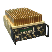
ChannelMaster TX1 Transmitter
Given the model number, the unit' configuration can be determined using the following:
AAAAA – CMTX1 – BBCC – X – YZ
Options
Emphasis Type
Specified Frequency Plan
Power Output
Model
Generalized Frequency Band Designator
Where:
AAAAA = mean frequency band center in GHz rounded to the closest GHz. This
number is then multiplied by 10. For multiple bands, each center frequency designation
is separated by a backslash "/".
BB = Used to identify the power output, per the following Power Output Designators:
Power Output is represented by Letters (A-Z; A=1, B=2, C=3, etc) for the analog power,
and Numbers (0-9) for the digital power. For example, a 5W Analog / 2W digital system
would be described with a power indicator of "E2". A Dual-Band system would have
two sets of power indicators, to show the power levels at both bands.
CC = Nucomm assigns a frequency chart number for each unique frequency channel
combination. Contact your Nucomm representative for further information.
X = Type Emphasis; 1 = NTSC and PAL M; 2 = PAL B/G
YZ = Miscellaneous options as listed below (append as many letters as needed)
M = FM only
M1 = COFDM only
M2 = FM / COFDM
M3 = FM / COFDM / DVBS
M4 = COFDM / DVBS
M5 = DVBS only
M6 = External 70MHz
Options that are not a standard part of the system, will be shown by shaded text as
shown here.