Revision 2.2
Installation
4-1
4. INSTALLATION
4.1 Unpacking and Inspection
Unpack and visually inspect the unit for
LCD, connectors, and surface area
damage. All claims should be filed with
the carrier. Save all shipping and
packing materials for possible re-use.
4.2 Pre-Installation Checkout
Connect the ChannelMaster RF output
through a 30 watt, 30 dB attenuator to a
spectrum analyzer. Verify the output
frequency and level correspond directly
to the transmitter front panel settings.
4.3 Mechanical Installation
The unit ships pre-assembled and
requires no mechanical installation other
than cabling. Optional accessories such
as Triax cable, tripod, direct mounting
antenna, or rack/vehicle mounting kits,
are shipped with necessary instructions.
4.4 Electrical Installation
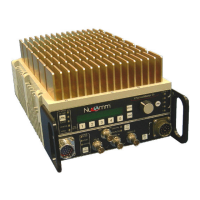
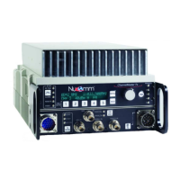
The unit front and back panels are
shown in Figure 4-1 and Figure 4-2.
Connector details are shown in Figures
4-3 to 4-5.
Power Connection (1)
The built-in power supply accepts 90 to
240 VAC (40 to 60 Hz) or +11 VDC to
+32 VDC without requiring any jumper
or switch settings. See Figure 4-5.
Nucomm ships a DC cable, and the
appropriate local AC line cord. Alternate
line cords are available upon request.
Optional "Standby" Power feature:
For power redundancy, the unit can be
configured to accept both AC AND DC.
ASI, SDI, Composite & 70MHz ports
All video inputs are made via 75 BNC
coaxial cables to the appropriate, clearly
marked, front panel port.
ASI (to 31.66845 Mbps) or SDI signals
are input via the ASI IN (2) or SDI IN (3)
ports. Composite or Baseband video is
input via VIDEO IN (4). 70 MHz is input
via the 70 MHz IN port (5). Select the
appropriate input type via the front panel
interface. See Section 5 for details.
Optionally, the unit can be fitted with an
ASI OUT port (not shown), for use as a
standalone ASI encoder.
AUDIO Inputs (6)
All audio inputs are made via this
connector. See Figure 4-4. The Digital
AES/EBU inputs are on Audios 1 & 3.
Only one Digital audio is available in the
standard “two audio” configuration.
RS232 connector (left side of unit)
This port is for control and monitoring
via RS232 or RS485. See Figure 4-3.
RF OUTPUT (7)
RF output is via a Type-N connector at
the rear of the unit. Directly connect a
suitable antenna, or a 50 , low-loss
coaxial cable (such as RG-214U)
between the RF Output and the antenna
connector.
POWER SWITCH and FUSES (8)
The unit has AC & DC fuses. The AC
fuse is 2.5 Amps (fast blow). The DC
fuse is 10 Amps (fast blow).