Operating Instruction and Documentation
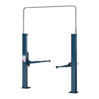
2.35 TSK
- 24 -
9.Installation and Initiation
9.1 Regulations for the installation
• The installation of the lift is performed by trained technicians of the manufacturer or its
distribution partner. If the operator can provide trained mechanics, he can install the lift by
himself. The installation has to be done according to this regulation.
• The standard lift must not be installed in hazardous locations or washing areas.
• An even installation place has to be provided. The foundations must be based in a frost
resistance depth, both outside and indoors, where you must reckon with frost.
• An electrical supply 3ph, N+PE/400V, 50Hz has to be provided. The supply line must be
protected with 16 Ampere time lag. The minimum diameter amounts to 2,5 mm².
The connecting point is in the operating unit.
• All cable ducts have to be equipped with protective coverings to prevent accidents.
9.2 Installation
A. Installation of the Canister
1. Built in empty cassette according to foundation diagram.
2. Fit the Installation-help-beams, properly spaced 50 mm (2") to the canister sides. The
bottom of the beam is the level for the top of the canister and the finished floor.
3. After having lowered the canister in to the pit, adjust the levelling screws to ensure that
the canister is level with the floor and plumb in the pit. Make sure that the canister is not
in contact with foreign metal parts in order to avoid electrolysis corrosion.
4. Anchor down the installation-help-beams. This is necessary to avoid the canister from
shifting when the pit around the canister is filled in.
5. Remove the top cover of the canister and install squared beam against deformation when
the pit is filled in.
6. Re-install the top-cover
7. Fill-in the pit around the canister with water-tight concrete or sand. Do not compact the
concrete.
8. Once the concrete is dry, open top-cover and remove the squared beam.
9. To avoid electrolysis corrosion, make sure that there are no metal parts lying around
inside the canister.
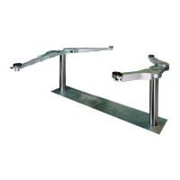
10 . Install the lifting-supports. Use the prescribed screws.
B. Installation of the Control Unit
(see hydraulic and electrical layout)
1 . Connect the Control unit to 3PH,N+PE,400V,50Hz in conformity with local requirements
and protected by a 16 Ampere time lag.
2. Run the two hydraulic hoses through the pipe duct in to the canister. Connect the hoses
to the lifting cylinders Tee-piece and the locking cylinder.