1 689 979 924N 26.11.07 53
3. Description of devices
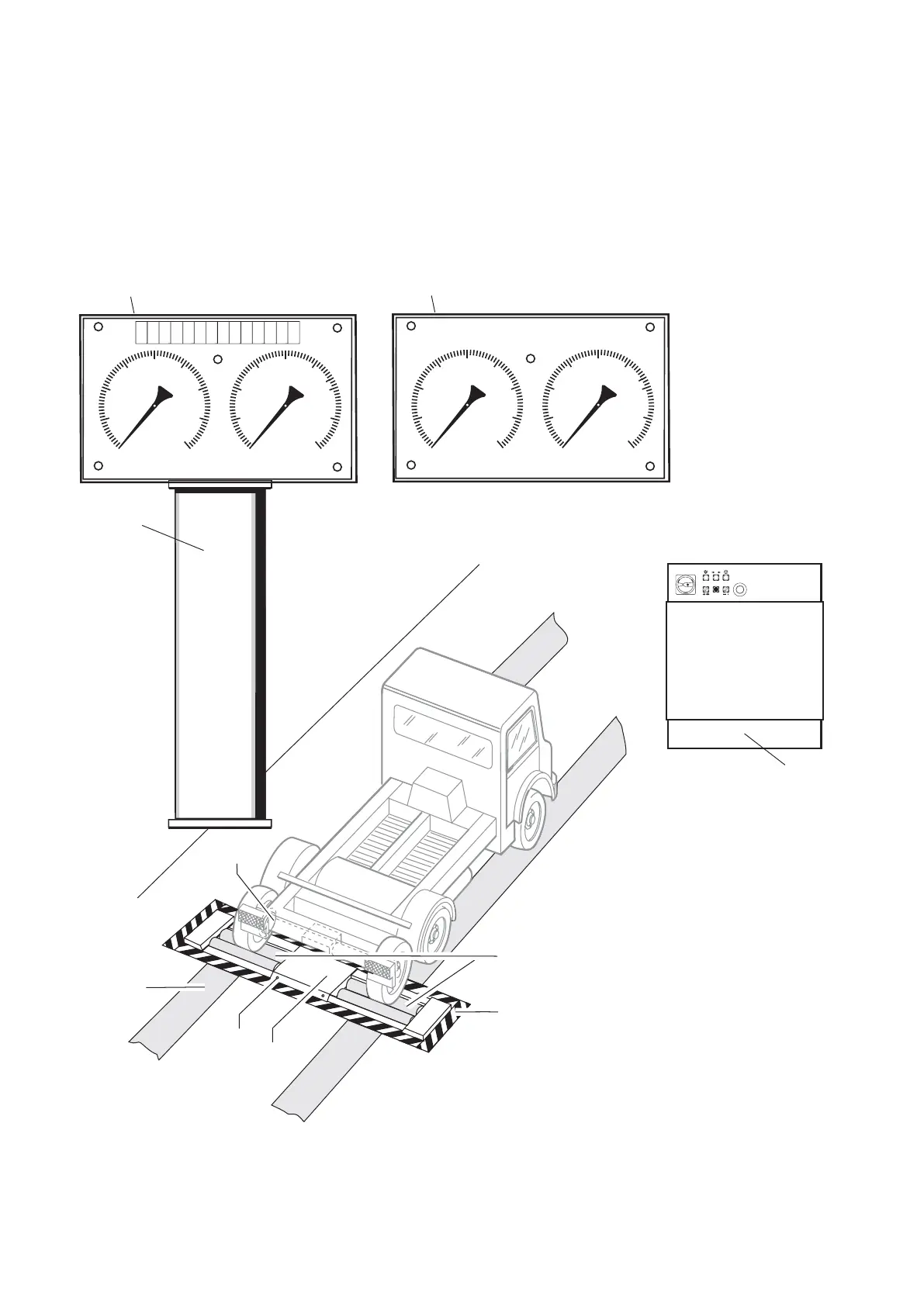
The brake test stand components are shown in the general
drawing (Fig. 1). An item number is allocated to each part. All
parts are briefly explained in the legend.
The brake test stand BT 610, 612, 640 or 642 consists of three
main systems:
- operating panel/control cabinet
- display unit
- left-hand and right-hand roller set
The display unit is mounted on a supporting column or a wall
bracket (both elements are options), fixed or pivoting.
453255/2P
24
23
22
18,19
20
32
20
25
30
40
10
0
kN
6
1
4
3
5
8
0
0 - 8kN
5
15
35
2
7
20
25
30
40
10
0
kN
6
1
4
3
5
8
0
5
15
35
2
7
20
25
30
40
10
0
kN
6
1
4
3
5
8
0
0 - 8kN
5
15
35
2
7
20
25
30
40
10
0
kN
6
1
4
3
5
8
0
5
15
35
2
7
1115 0220
99
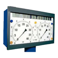
Figure 1, Overview:
10. Display cabinet
11. Display cabinet with 14-figure
digital display (optional extra)
15. Supporting column (option)
18. Left-hand roller set
19. Right-hand roller set
20. Warning paint
22. Cover sheet, middle
23. Screws for cover sheets
24. Guiding mark
32. Axle to be checked
99. Operating panel/control cabi-
net
gelampe
„Bremskraft-Differenz“
2.
Anzeige LKW
2.1 Simultananzeige LKW
11 10
15
0
 Loading...