LPC2468 IRD Kit 1.2 Quick Start Guide, rev. 1.0 Page 7 of 8
6.0 Connection Headers Reference Table
The following list is a description of all the jumpers and connection headers on the IRD Baseboard
(version 1.3). Additional information can be found in the IRD schematic and User Manual
documents.
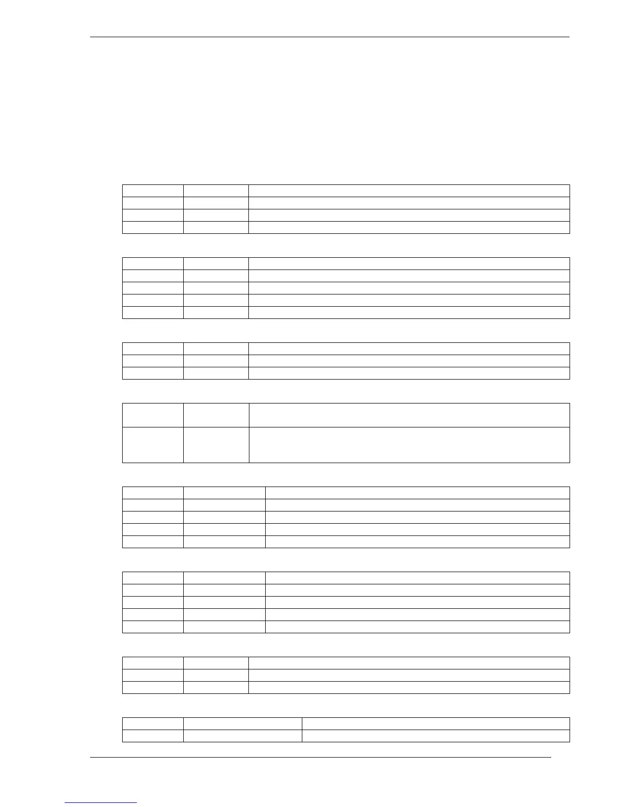
JP4 & JP5 – CAN Analyzer Connectors
Pin Label Function
1 CANH Connects CAN Analyzer to CANH signal of TJA1040
2 GND Ground connection
3 CANL Connects CAN Analyzer to CANL signal of TJA1040
CAN_Test – CAN Loopback Interface
Pin Label Function
1 CAN2-L CAN2 Channel CANL Signal
2 CAN1-L CAN1 Channel CANL Signal
3 CAN2-H CAN2 Channel CANH Signal
4 CAN1-H CAN1 Channel CANH Signal
CAN1_PWR & CAN2_PWR – CAN Slave Port Power Connectors
Pin Label Function
1 +5VDC +5VDC Power Supply From External Supply or POE Module
2 CAN-PWR Connects +5VDC to CAN Slave Unit via pin 9 of DB9 Connector
JP8 & JP10 – ISP Mode Selection
JP8 P2_10 The microcontroller is placed in ISP mode when this jumper is
connected, enabling FlashMagic to program the microcontroller.
JP10 RESET The microcontroller is held in reset for ISP programming when this
jumper is connected, enabling Flash Magic to program the
microcontroler
JP9 – UART0 DCE/DTE Selection
Pin Label Function
1 T1OUT RS-232 Serial Data Output from UART0
2 UART0 Pin2 Pin 2 of the UART0 DB9 Connector
3 UART0 Pin3 Pin 3 of the UART0 DB9 Connector
4 R1IN RS-232 Serial Data Input to UART0
JP12 – UART1 DCE/DTE Selection
Pin Label Function
1 T2OUT RS-232 Serial Data Output from UART1
2 UART1 Pin3 Pin 2 of the UART0 DB9 Connector
3 UART1 Pin2 Pin 3 of the UART0 DB9 Connector
4 R2IN RS-232 Serial Data Input to UART1
J_TEMP – External Temperature Sensor Connector
Pin Label Function
1 D- External Temperature Sensor negative (White Wire) connection
2 D+ External Temperature Sensor positive (Red Wire) connection
JP18 – 3.3VDC Source Selection
Pin Label Function
1 +3.3VDC IC13 (Onboard 3.3VDC Regulator) Output

 Loading...


