REGULATORS
DELTA 4 SECOND STAGE
© 2002 Design, 2005
PG-6
OCEANIC® Product Service Guide
Doc. 12-2803-r02 (10/3/10)
16. Remove the POPPET (15), POPPET SPRING (16), WASHER
(18), SPACER (19), LEVER (17), and LOCK NUT (20) by holding
the POPPET with the Poppet Tool while turning the LOCK NUT
counterclockwise using a 1/4" nut driver. To avoid a sudden ejec-
tion as they are disengaged, continuously apply a slight amount
of inward pressure to the POPPET and the LOCK NUT.
17. Examine the SPACER (19) for deterioration. Discard if found.
Discard the LOCK NUT (20) and WASHER (18), and DO NOT
attempt to reuse them.
18. Examine the LEVER ARM (17) and compare with new to ensure
that it is not bent or distorted in any way. Discard if distortion is
found.
19. Examine the POPPET SPRING (16) with a magnier and compare
with new to ensure correct tension and length. Discard if found
to be weakened or corroded.
20. Remove the POPPET SEAT (14) from the POPPET (15) with the
use of a dental pick. Discard and DO NOT attempt to reuse it.
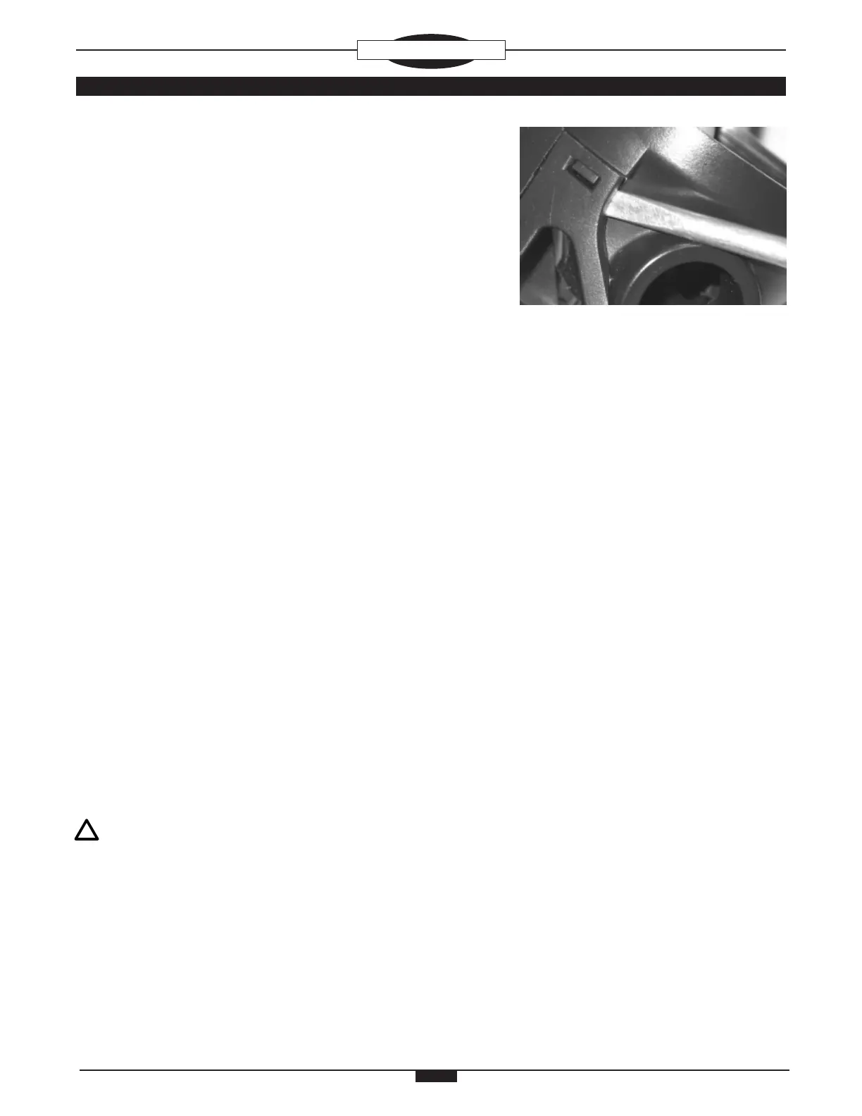
21. Using the at end of a brass O-ring Tool or a thin plastic probe,
carefully lift the Retaining Tab Slats of the EXHAUST COVER
(6) from the Retaining Tabs located on the base of the HOUS-
ING ASSEMBLY (5) (Fig. 9). Once the EXHAUST COVER is
disengaged from the retaining tabs, push straight down on the
Exhaust Porting of the EXHAUST COVER to remove it from the
HOUSING ASSEMBLY.
22. Inspect the overall condition of the HOUSING ASSEMBLY (5),
and the EXHAUST COVER (6) to ensure they are free of any
stress cracks or other distortions. Ensure that all Threading on
the HOUSING ASSEMBLY is in good condition. Discard either
if any distortion or damage is found.
23. Using a soft probe, inspect the condition of the EXHAUST VALVE
(7) to ensure that it is supple and free of any tears or corrosion,
and that it seals completely around the Seating Surface of the
HOUSING ASSEMBLY (5).
NOTE: Provided that the EXHAUST VALVE (7) is in good
condition, removing it is not necessary. The HOUSING
ASSEMBLY (5) may be cleaned with the EXHAUST VALVE
attached. (Refer to the Cleaning Section of this manual.)
24. If the EXHAUST VALVE (7) requires replacement, it may be
removed by grasping it at the Flange and pulling it straight out,
snipping the Retainer Stem if necessary. Discard.
25. Inspect the VENTURI SWITCH (35) for smooth even operation,
ensuring there is no resistance throughout its range of move-
ment. Inspect for signs of debris trapped within the VENTURI
SWITCH Mechanism, and ensure there is no corrosion or rust
on the SWITCH RETAINING RING (37).
Fig. 9