REGULATORS
DELTA 4 SECOND STAGE
© 2002 Design, 2005
PG-7
OCEANIC® Product Service Guide
Doc. 12-2803-r02 (10/3/10)
NOTE: Provided that the VENTURI SWITCH Mechanism is in
good condition, removing it is not necessary. The HOUSING
ASSEMBLY (5) may be cleaned with the VENTURI SWITCH
attached. (Refer to the Cleaning Section of this manual.)
26. If disassembly of the VENTURI SWITCH Assembly is needed,
proceed by closely adhering to the following steps:
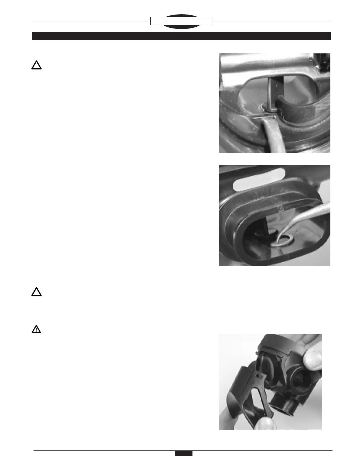
A. Remove the SWITCH RETAINING RING (37) by pushing on
the exposed Tip of the RETAINING RING with a brass O-ring
Tool until the Body of the RETAINING RING is no longer seated
in the Groove on the VENTURI SWITCH (35) (Fig. 10).
B. Place the end of the brass O-ring Tool through the Mouthpiece
opening in the HOUSING ASSEMBLY (5) and into the space
between the Body of the SWITCH RETAINING RING (37) and
the VENTURI SWITCH (35). Using caution not to damage the
HOUSING ASSEMBLY, slowly pull the SWITCH RETAINING
RING away from the VENTURI SWITCH to remove it (Fig. 11).
C. Grasp the VENTURI SWITCH (35) by the Adjustment Tab
and pull it straight up and out of the HOUSING ASSEMBLY (5) to
remove it. Remove and discard the VENTURI SWITCH O-RING
(36), and DO NOT reuse it.
D. Closely examine the VENTURI SWITCH (35) and the SWITCH
RETAINING RING (37) for signs of distortion, cracks, corrosion,
rust, or other damage. Discard if found.
REASSEMBLY PROCEDURE
NOTE: Prior to Reassembly, it is necessary to inspect all
Parts, both new and those that are being reused. Check to
ensure that O-rings are clean and supple, and that every Part
and Component has been thoroughly cleaned and dried.
WARNING: Use only genuine Oceanic Parts, Subassemblies,
and Components whenever assembling Oceanic products.
DO NOT attempt to substitute an Oceanic Part with another
manufacturer’s, regardless of any similarity in shape, size,
or appearance. Doing so may render the product unsafe,
and could result in serious injury or death of the user.
1. Replace the EXHAUST VALVE (7), if removed, into the HOUSING
ASSEMBLY (5) by gently pulling the Retainer Stem through the
HOUSING ASSEMBLY until the Retaining Flange is inside and
properly seated.
2. Replace the EXHAUST COVER (6) onto the Exhaust Tee por-
tion of the HOUSING ASSEMBLY (5) by holding the EXHAUST
COVER at a slight angle to the HOUSING ASSEMBLY with the
Bottom raised and mating the Top of it with the Hinge Tabs on
the HOUSING ASSEMBLY. Ensure that the Top is aligned, then
Fig. 12
Fig. 10
Fig. 11