Page 2 of 2
For Reference Only
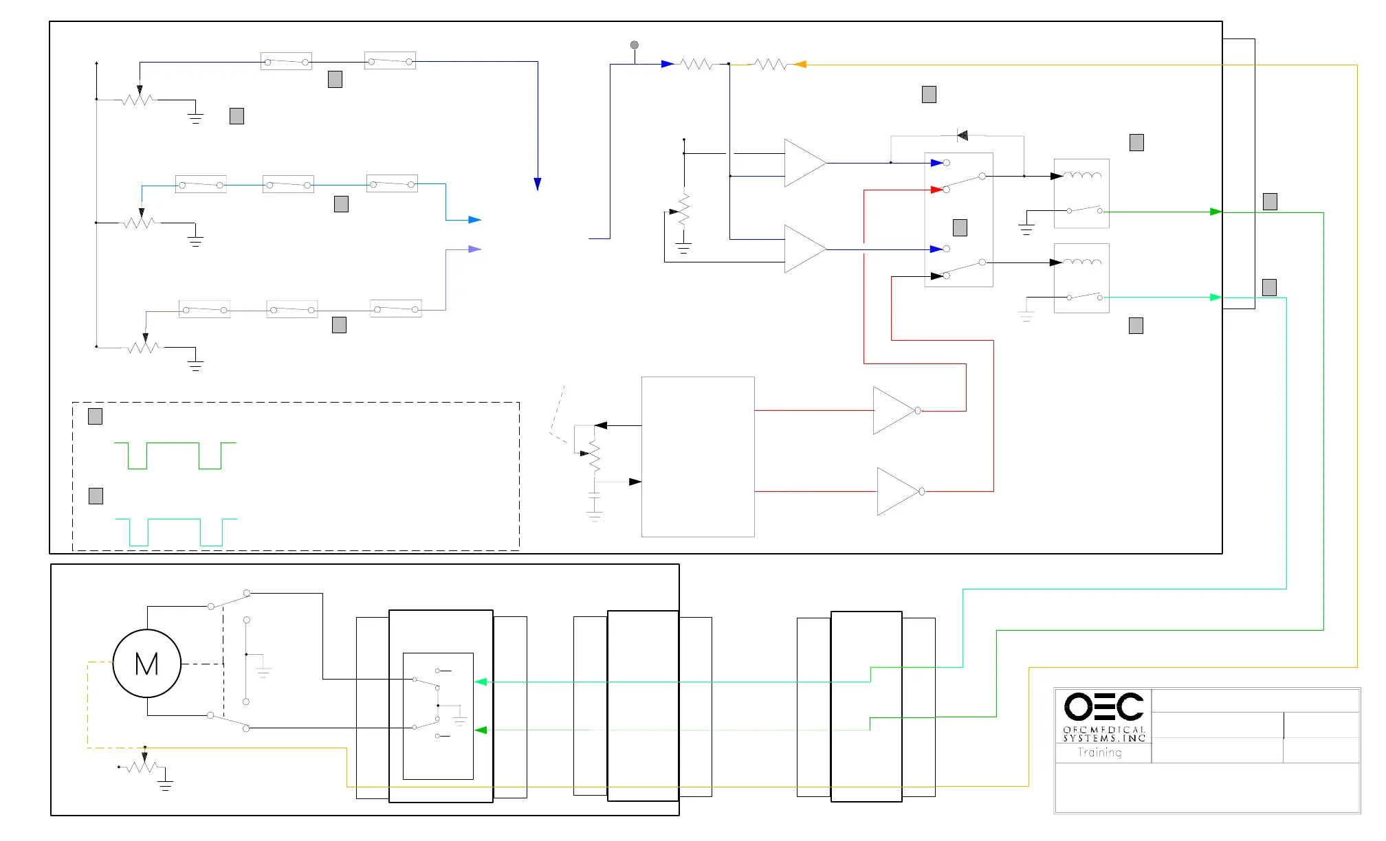
COLLIMATOR CONTROL
IRIS MOTOR DRIVE LOGIC
03/17/97
IRIS_S.DS4
SERIES 7600
NORMAL
MAG or HAND
MAG and HAND
R29
17 71
77
1
17
7
1
K8
K2
NC
NC
14
7
14
K1 K8
K2
NC
NONO
R30
R58
K1
K8
K2
NCNC
NO
7
14
The desired Iris
position signal
out of K2-7 is
sent to the Iris
comparator circuit
+
-
+
-
+12V
U6
U7
2
3
5
5
2
3
IRIS CLOSE
IRIS OPEN
R34
R52
K7
9
11
13
8
6
4
+16V
-MIBZ
-MIBA
K6
K5
6
2
7
14
14
2
7
6
B101 BOARD
Desired Iris position
13
U1
IRIS
CONTROL
LOGIC
PAL U2
PAL U3
TRANS T7
NAND U9
R36
Manual
Iris speed
adjustment
+RBLMIN
+RBLPLU
U1
4
3
14
ST1
C20
A20
A21
R2
Actual Iris position
POTIM
IRIS
POT
+12V
LIMIT SWITCH
B45
BOARD
FILTER
BOARD
B1OO
BOARD
XP3P2 X3
P3
DRIVE
CIRCUITS
10
5
7
10
11
12
10 10
11
11
12
12
10
11
12
A21
A20
C20
ST1
ST4
XRAY HEAD ASSEMBLY
IRIS CLOSE
IRIS OPEN
MP3
Relay contacts (K1, K2, K8) are shown
in the proper condition for each respective
function unless indicated otherwise
K5,K6 & K7 are shown in
the de-energized condition
LIMIT SWITCH
16V
16V
-MIBA
-MIBZ
OPEN
CLOSE
K5
K6
1
1
1
1
2
2
2
2
3
4
3
Aprox 12.5VDC (chassis Gnd) measured with a DVM when active (close)
16V
0V0V
measured with a scope when active (close)
4
Aprox 12.5VDC (chassis Gnd) measured with a DVM when active (open)
16V
0V0V
measured with a scope when active (open)
(15 cm / 6 inch)
(23 cm / 9 inch)
(10 cm / 4 inch)
NOTES:
IRIS
MOTOR
Used and Refurbished C-Arms are Available from www.SharpMedical.com - Call us at 800-969-9800
An Independent C-Arm Service Provider. This PDF provided for research / historical purposes only.
 Loading...


