MSM80C154S/83C154S/85C154HVS
208
5.9 Precautions When Driving External Transistors by Ouasi-bidirectional
Port Output Signals
The following points must be carefully considered when quasi-bidirectional ports are used to
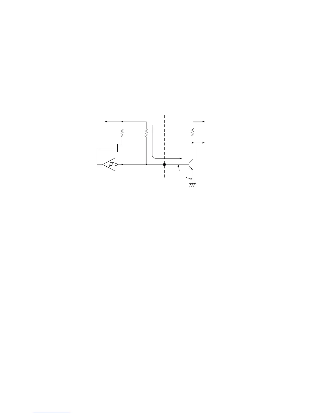
drive a transistor by the circuit shown in Figure 5-12.
Even though the CPU output in this circuit is at “1” level, the port output pin level may be
clamped by the base-emitter voltage VBE (0.7V) of an external NPN transistor, resulting in a
pin level of “0”.
Figure 5-12 NPN transistor direct connection circuit
When the pin level is dropped to “0”, the CPU disconnects the 10 kW pull-up resistance from
the power supply, leaving only the 100 kW pull-up resistance connected. Since the base
current IB of an external NPN transistor is supplied via the 100 kW resistance, the transistor
collector current IC may be reduced to a level insufficient for driving purposes.
To resolve this problem, diode can be inserted between the transistor base and CPU pin as
indicated in Figure 5-13 to achieve a pin level of “1” by level shift. or by using a PNP transistor
as indicated in Figure 5-14 where the external transistor is driven by a “0” level port output,
this problem is solved.
VCC
10kΩ
IB
VCC
P
100kΩ
OUT
CPU "1" OUT
.
.
V
BE=0.7V