Oliver 2018 – 18” Lathe
C
ontents
F
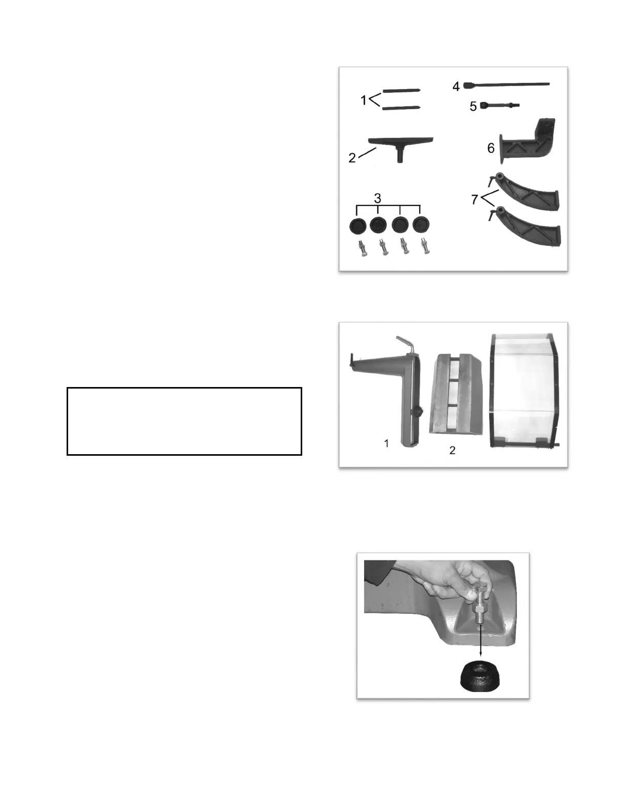
igure 1
1. Comparator Centers (two)
2. Tool Rests
3. Levelling Pads and Bolts
4. Knockout Rod
5. Motor Tension Rod
6. Comparator/Guard Support Bracket
7. Comparator/Guard Brackets
Figure 2
1. Outboard Tool Rest Holder (Optional)
2. Bed Extension (Optional)
3. Guard
Uncrating the Machine
Retain all packaging materials in case it becomes
necessary to ship the machine to another site.
Machine Preparation and Setup
WARNING!
The equipment used to lift this machine must
have a rated capacity at, or above the weight
of the lathe. Failure to comply may cause
serious injury!
T
he lathe can be lifted off the skid from over head
using slings ran under the lathe bed.
T
he lathe must be positioned on a smooth, level
surface. Install the leveling bolts and pads (3,
Figure 1) under the four corners of the lathe.
C
lean all rust protected surfaces with a
commercial solvent. Do not use acetone,
gasoline, lacquer thinner or any type of
flammable solvent, or a cleaner that may damage
paint. Cover cleaned surfaces with WD-40 or a
20W machine oil.
I
nsert the leveling bolts as shown in Figure 4.
Place a level on the bed of the lathe and adjust
leveling bolts until the machine is resting level on
the pads. Tighten the hex nuts against the base
of the lathe to keep the leveling bolts from turning.
F
igure 1
F
igure 2
Figure 4
Pictures and illustrations may vary from
actual product.