Face Plates – Removal and Installation
(cont.)
O
utboard
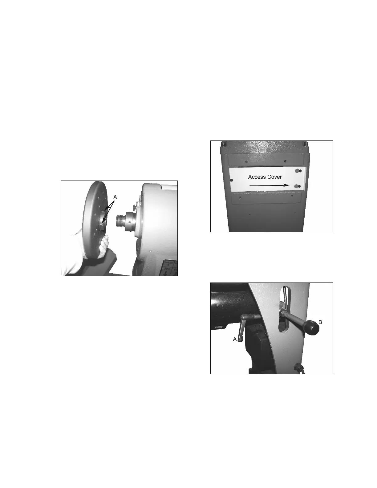
1. The outboard face plate removes in the
s
ame fashion as the inboard. Figure 20
shows the face plate already removed from
the spindle. Before removing, loosen the
two set screws ‘A’ then lock the spindle
using the indexing pin as described in the
inboard face plate removal instructions.
The face plate diameter should be large
enough to give sufficient torque to unscrew
by hand. This is done in a
counterclockwise rotation. If the faceplate
does not budge, insert two metal dowels
into two of the mounting holes on the face
of
the plate. Then use a leverage bar
between the two dowels to loosen the face
plate.
F
igure 20
2. U
se the reverse procedure to install th
e
f
ace plate back onto the spindle. Hand
tighten only.
H
i/Lo Range Belt change
Moving the position of the poly-v belt to the other
step on the motor sheave and the idler sheave
changes the Hi or Low speed range on your
Oliver lathe.
1. R
emove the access panel located under th
e
outboard face plate a shown in Figure 21.
Loosen the three screws just enough so that
the panel can slide free.
F
igure 21
2. See Figure 22 and loosen the lock handle
‘A’ and lift up the motor using the handle ‘B.
Once it is up all the way, tighten into plac
e
w
ith handle ‘A’.
F
igure 22