Adjustments
Tailstock
Depending on the length of your work piece, the
tailstock can be moved accordingly. Simply push
or pull handle A of Figure 15 to loosen and allow
the tailstock to slide to the correct position. Once
in position lock it into place with handle A. Fine
adjustment can be achieved by turning the
handwheel to lengthen or shorten the tailstock
spindle.
Figure 15
Cam Adjustments
If the tool rests or tailstock do not tighten to the
bed lathe when the locking handle is engaged, it
may be necessary to tighten the locknut as seen
in Figure 16. The adjustment is the same for all
three.
F
igure 16
T
ool Supports
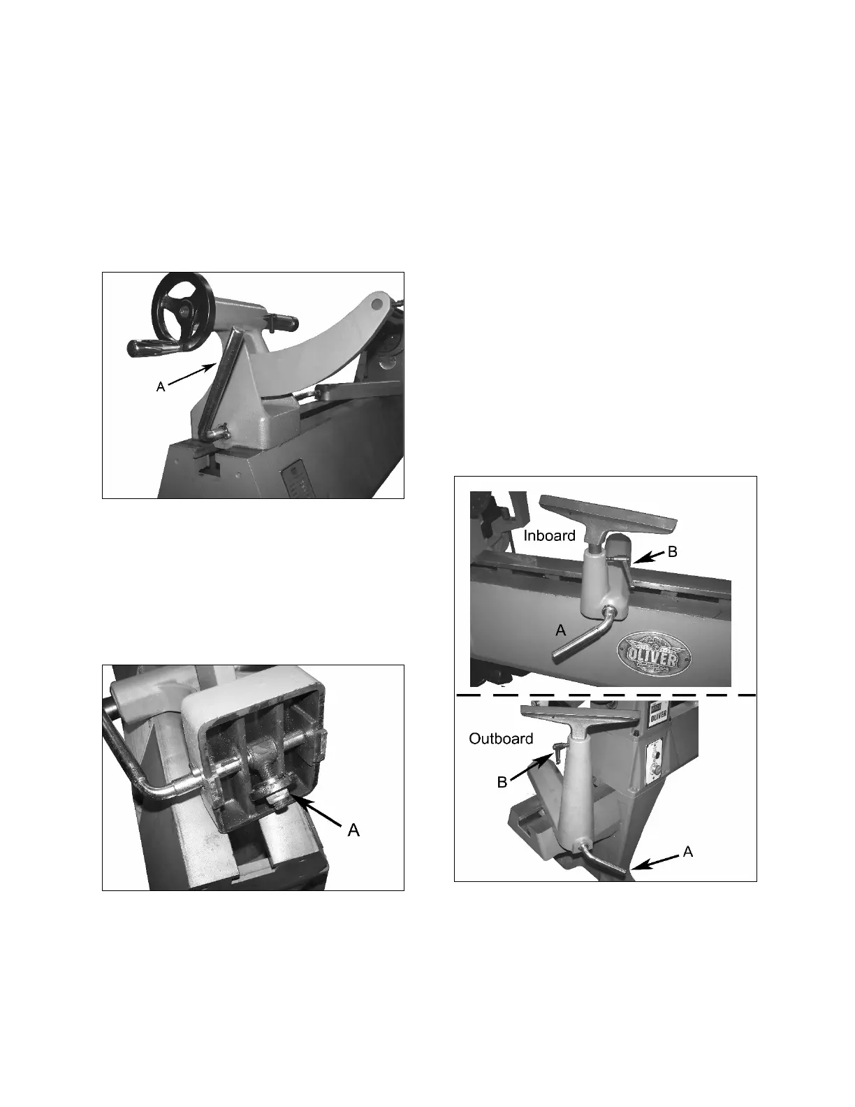
Your Oliver lathe comes with an inboard and if
ordered with optional bed extension and outboard
tool rest as seen in Figure 17. Each tool rest can
be adjusted for height, position on the bed, and
angle to the work piece.
Loosen the lock handle A to slide the rest forward
or back as well as to angle it with respect to the
bed. Once set to the desired position use handle
A again to lock it into place before using the lathe.
Loose handle B to adjust the height and angle of
the tool rest itself. Once set, lock it into place
before using the lathe. Note that the small handle
B is a ratchet type handle and can be positioned
so that it is out of the way when working.
A
lthough not seen in the picture, there is another
hole on the opposite side in which the small
handle can be inserted if desired.
Figure 17