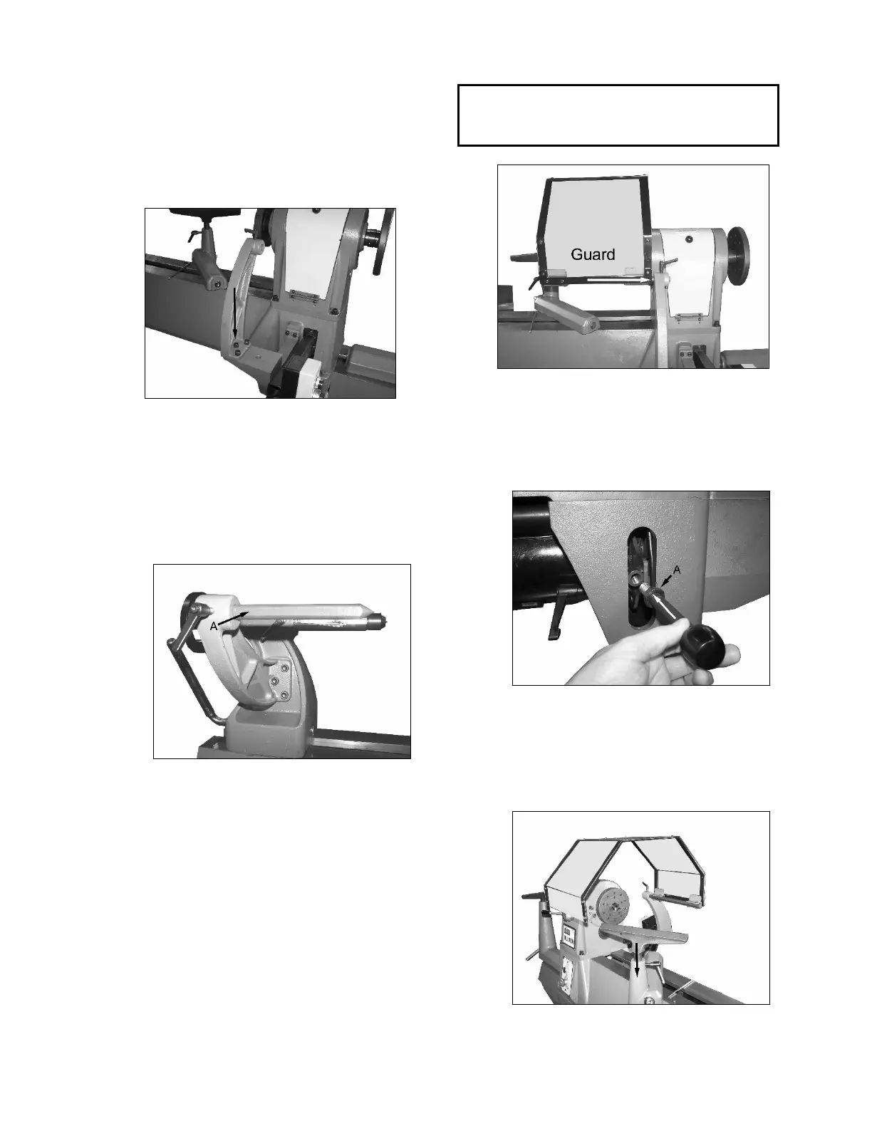
Assembly (cont.)
5. Moun
t the headstock si
de
c
omparator/guard bracket on top of the
support as shown in Figure 10. Us
e
the supplied 6mm Allen head bolts.
Figure 10
6. Moun
t the second comparator bracket
to the tailstock as shown in Figure 1
1
us
ing the supplied 6mm Allen head
bolts. As well, the comparator pin A has
been installed. Notice the flat part of t
he
pi
n faces the bolt of the lock handle.
F
igure 11
7. Your Oliver lathe is equipped with a
s
afety shield. Install the mounting post
of the shield, in the direction shown by
the arrow in Figure 12, into th
e
c
omparator/guard bracket and lock int
o
pl
ace with the lock handle. Loosen t
he
lock handle to adjust the guard position
as
necessary and then re-tighten.
I
f desired, the safety shield can b
e
r
emoved in order to install the second
comparator pin.
CAUTION!
Eye protection must always be worn whether
the safety shield is installed or not!
Figure 12
8. I
nstall the motor tension rod as shown i
n
F
igure 13. Once threaded in, lock into
place with the jam nut A.
Figure 13
9. T
he inboard tool rest can now be
installed in its holder as shown i
n
Figure 14. Once set in place lock it
using the handle A.
Figure 14