23
BXFMA
ASSEMBLY
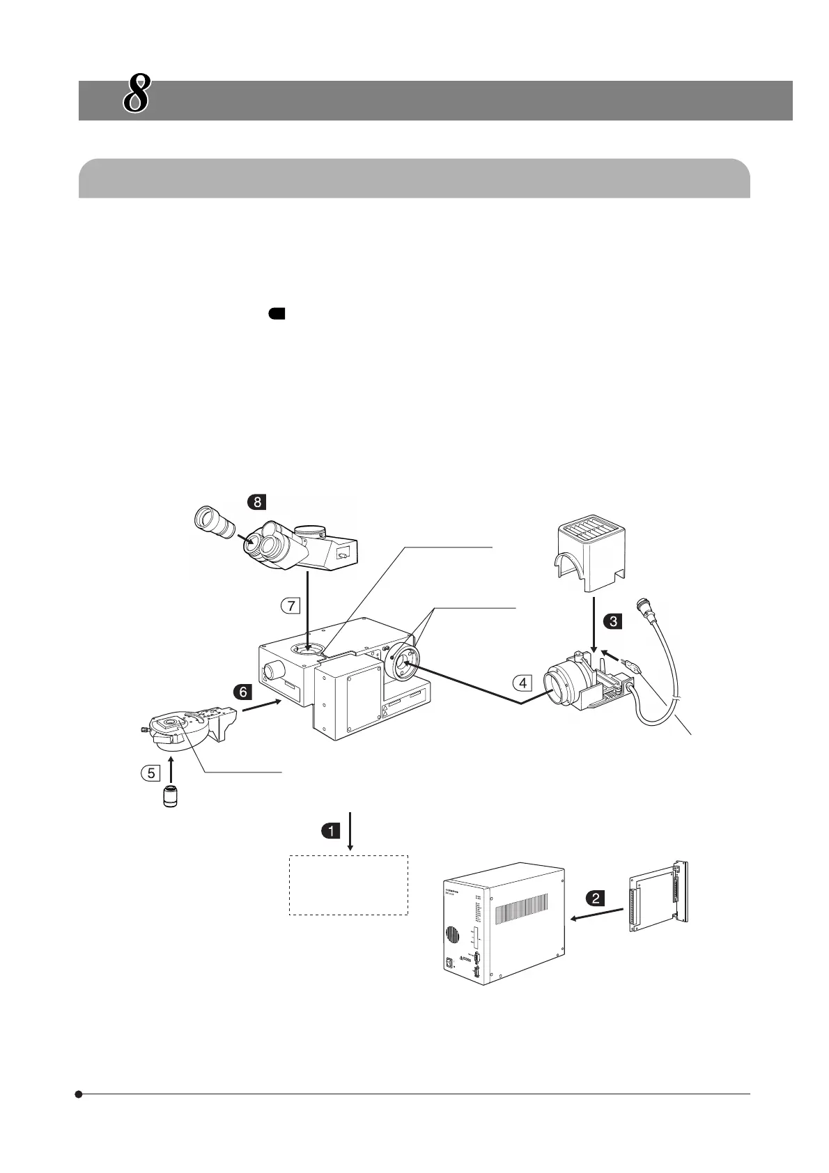
8-1 Assembly Diagram
· The diagram below shows the sequence of assembly of the various modules. The numbers indicate the order of assembly.
· The module model numbers shown in the following diagram are merely the typical examples. For the modules with which
the model numbers are not given, please consult Olympus or the catalogues.
# When assembling the system, make sure that all parts are free of dust and dirt, and avoid scratching any parts or
touching glass surfaces.
}Assembly steps enclosed in will be detailed on the subsequent pages. Please also refer to the instruction manuals
provided with the modules.
}For the connection of modules, see also Chapter 1, “System Diagram” on page 4.
Eyepiece
WHN10X (FN 22)
35WHN10X (FN 22)
SWH10X-H (FN 26.5)
35SWH10X (FN 26.5)
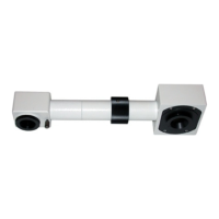
Observation tube
U-BI30-2 (FN 22)
U-TR30-2 (FN 22)
U-TBI3 (FN 22)
U-SWBI30 (FN 26.5)
U-SWTR-3 (FN 26.5)
U-ETBI (FN 22)
Observation tube
clamping screw
Lamp housing
clamping screw
Motorized revolving
nosepiece
U-D5BDREMC
U-D6REMC
U-P5REMC
U-D5BDREM
U-D6REM
Mount dovetail
Objective
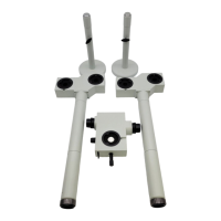
Motorized Illuminator
with Motorized
Focusing Unit
BXFMA-F
Installation on the
User’s System
100 W halogen lamp
housing
U-LH100-3
U-LH100L-3
100 W halogen bulb
12V100WHAL-L
12V50WHAL-L
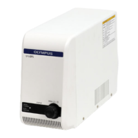
Control box
BX-UCB
Z-board
U-ZPCB(T2)
AF board
U-AFA1-CB