4
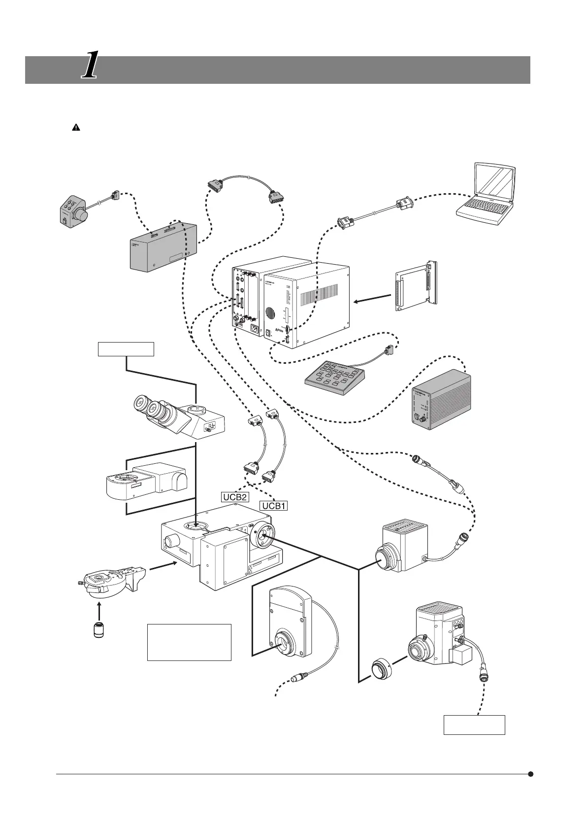
SYSTEM DIAGRAM
}The modules marked * are not required when a PC is used to control all operations from the PC.
The PC used in this system should meet the requirements by IEC60950. Be sure to use an Olympus-designated
connection cord. If a non-designated connection cord is used, Olympus cannot guarantee any performance of the
system.
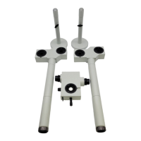
Focus Adjustment
Knob Unit
U-FH
*
Focus Adjustment
Knob Interface
U-IFFH
*
Connection cable
*
(50-pin)
(Rear panel)
RS232C cable
PC
(BX2-BSW
installed)
Control Box
BX-UCB
Z-Board
U-ZPCB(T2)
AF Board
U-AFA1-CB
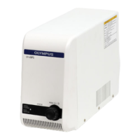
Power Supply
Unit
TH4
*
Hand Switch
U-HSTR2
*
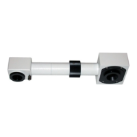
TV system
Observation tube
· U-BI30-2
· U-TR30-2
· U-TBI3
· U-TUL, etc.
Active AF Unit
U-AFA1M
Motorized Revolving
Nosepiece
· U-D5BDREMC
· U-D6REMC
· U-P5REMC
· U-D5BDREM
· U-D6REM
Objective
Connection
cable
(50-pin)
Connection
cable
(36-pin)
Extension Cord
U-RMT
High-Intensity
Lamp Housing
· U-LH100HG
· U-LH100HGAPO
· U-LH50MH
· U-LH75XEAPO
100 W Halogen
Lamp Housing
· U-LH100-3
· U-LH100L-3
Auxiliary ring
(provided with the
BXFMA-F)
Filter Wheel
U-FWR
(Note)
Special power
supply
Motorized Illuminator
with Motorized
Focusing Unit
BXFMA-F
Surface for installation
on system:
· Bottom panel
· Left side panel
Connect to FW1, 2 or 3
of BX-UCB
()
(Note) The cable of the U-FWR filter wheel runs close to the lamp housing when the filter wheel is attached.
Position the cable so that it does not come in contact with the lamp housing.