OS100 Series - Operation
3
3-3
3.3 Atmospheric Quality
Environments with smoke, dust, and fumes dirty up the optical lens, and
cause erroneous temperature readings. To keep the surface of the optical
lens clean, the air purge collar accessory is recommended, OS100-AP, See
Fig. 3-7.
3.4 Measuring Temperature
Before starting to measure temperature, make sure that the following
check list is met:
The power and analog output connections are made (Fig. 2-1).
The sensor head is connected to the main unit.
The slide switch (SW1) on the main board is set to real time (Fig. 3-1).
The target is larger than the optical field of view of the sensor head
(Fig. 3- 3 ).
The emissivity adjustment on the main board is set properly (Fig. 3-1).
The output load is within the product specification.
On OS102 transmitters, follow these additional steps:
The temperature display is set to °F or °C (Fig. 3-4)
For 4-20mA output models, make sure an output load is added, ie. 250
ohms.
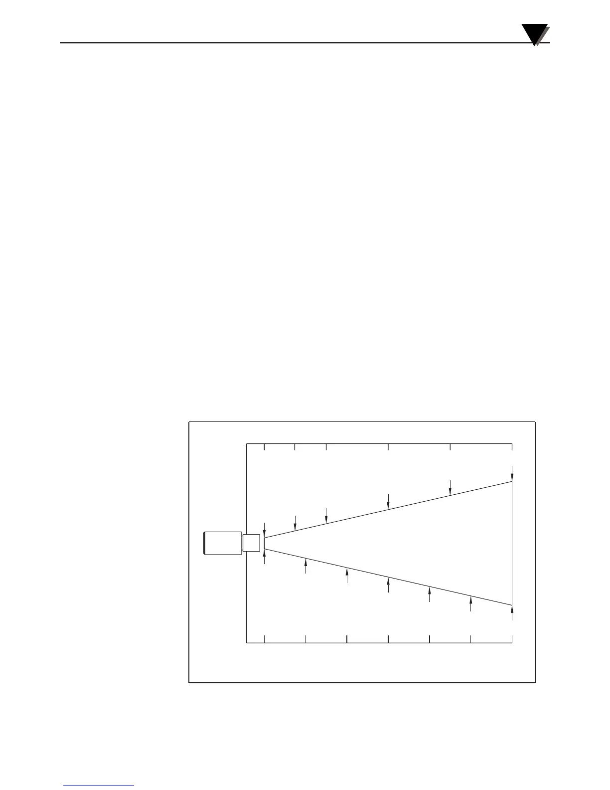
Figure 3-3. Optical Field Of View
SPOT DIA.* (CM)
SPOT DIA.* (IN)
DISTANCE: SENSOR TO OBJECT (IN)
D:S=6:1
1cm@0
0
20
3.3
40
6.6
60
10.0
80
13.0
100
16.0
122
20.0
0.4"@0"
2.0"
1.0"
4.0"
6.0"
8.0"
48"
36"
24"
12"6"
0"
DISTANCE: SENSOR TO OBJECT (CM)
* SPOT DIAMETER MEASURED AT 90% ENERGY
 Loading...