OS100 Series - Installation
2
The following describes the ordering information:
OS102 or OS101 - MA - *, **, where
The following optional accessories are available:
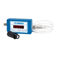
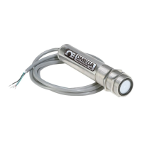
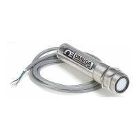
Here are the Features of OS101 and OS102 infrared transmitters:
2.2 Electrical Connection
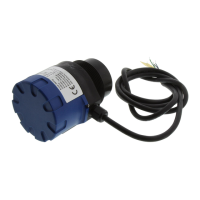
Sensor Head Cable - The Sensor head is pre-wired to a 1.8 m (6 feet)
shielded cable. Plug & lock-in the male connector to the mating female
connector on the aluminum housing.
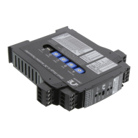
Power & Output Connection - Open the cover of the main aluminum
housing. Slide the cable through the strain relief and connect the wires to
the terminal block on the board as shown in Fig. 2-1. For Alarm output
connection, refer to Fig. 2-2.
2-1
Model No. Description
OS100-MB Mounting Bracket
OS100-DR DIN Rail Mounting adapter
OS100-WC Water Cooling jacket
OS100-AP Air purge collar
OS100-LS Laser Sighting
OS100-CA15FT Sensor Head Extension Cable (4.6 m, 15")
OS100-CA25FT Sensor Head Extension Cable (7.6 m, 25')
TX8-100 8 Conductor stranded Shielded cable (30 m, 100')
PSU-93 Unregulated 16-24 VDC Power Supply
CAL3-IR NIST Traceable Calibration
Features OS101 OS102
Accuracy 2% Rdg or 4°F (2.2°C)
Temp Range 0-1000°F (-18 to 538°C)
Emissivity 0.1 to 0.99 Adj.
Field of View 6 to 1
Alarm Output Standard
1mV/Deg. Output Standard
4-20mA Output Standard
0/5 VDC Output Standard
K Type T/C Std. ––
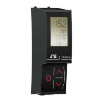
LED Display –– Std.
Main Housing 65.5 x 30.5 x 115.3 mm 65.5 x 55.9 x 115.3 mm
(2.58" x 1.2" x 4.54") 2.58" x 2.2" x 4.54"
MA - 4/20 mA output
V1 - 0 to 5 VDC output
K - Thermocouple output, K type
MV - Millivolt output
C - 1 mV/°C output
F - 1 mV/°F output
HT- High
temperature
sensor head
 Loading...